Low profile mount for flat panel electronic display

a technology for electronic displays and mounts, applied in washstands, television systems, light supports, etc., can solve the problems of installation difficulty, installation difficulty, and installation difficulty, and achieve the effect of enabling tilt positioning of the display

Active Publication Date: 2015-08-18
LEGRAND AV INC
View PDF372 Cites 24 Cited by
  • Summary
  • Abstract
  • Description
  • Claims
  • Application Information

AI Technical Summary

Benefits of technology

[0010]Embodiments of the present invention provide a low-profile display mount that overcomes the drawbacks of the prior art. According to embodiments of the invention, a display mount includes a wall interface plate, and one or more tilt assemblies. Each tilt assembly presents a display receiving surface for receiving the back side of the display thereon. The tilt assemblies are shiftable between a wall confronting position wherein the back side of the display is proximate and substantially parallel with the wall surface, and a tilt position wherein the top of the display is tilted away from the wall. The tilt assemblies are configured so that points spaced apart forwardly of the display receiving surfaces translate along a substantially horizontal axis as the tilt assemblies are shifted between the wall confronting position and the tilt position. Advantageously, the display can be attached to the mount so that the points are horizontally registered with a center of gravity of the display such that the display is self-balancing at any point along the travel between the wall confronting position and the tilt position. The mount may enable the back side of the display to be spaced apart between only about 0.25 to 0.50 inch, and preferably 0.30 inch, from the wall when in the wall confronting position, while still enabling tilt positioning of the display.

Problems solved by technology

These prior mounting devices, however, have drawbacks.
One drawback of prior low-profile mounting devices is that they generally do not enable access to the rear of the display for the connection of cables and wires once the display is in place on the mount.
Instead, the installer must wrestle with a sometimes heavy and awkward display device to connect the wires before mounting on the wall.
Further, the wires may then interfere with attachment to the wall once connected.
Another drawback to prior low-profile display mounts is that they often do not provide secure attachment to the wall so as to prevent inadvertent detachment of the display.
A further drawback of many prior low-profile display mounting devices is that they are awkward and difficult to manipulate.
An installer attempting to mount the display device may have to lift a heavy or large size display into an awkward position in order to attach the device to a wall mount, or may have to manipulate complicated catches or latching devices while simultaneously lifting.
Another drawback of previous low profile mounts is that they represent a compromise between closeness of the display to the wall surface and the range of tilting motion available for the display.
If the mount has a very low profile, the tilt range of the mount is limited because the edge of the display contacts the wall when tilting.
If the mount is made thicker to accommodate the tilt motion of the display, the desirable aesthetic of a display mounted close to the wall surface is lost.

Method used


Image

  • Low profile mount for flat panel electronic display
  • Low profile mount for flat panel electronic display
  • Low profile mount for flat panel electronic display

Examples


Embodiment Construction

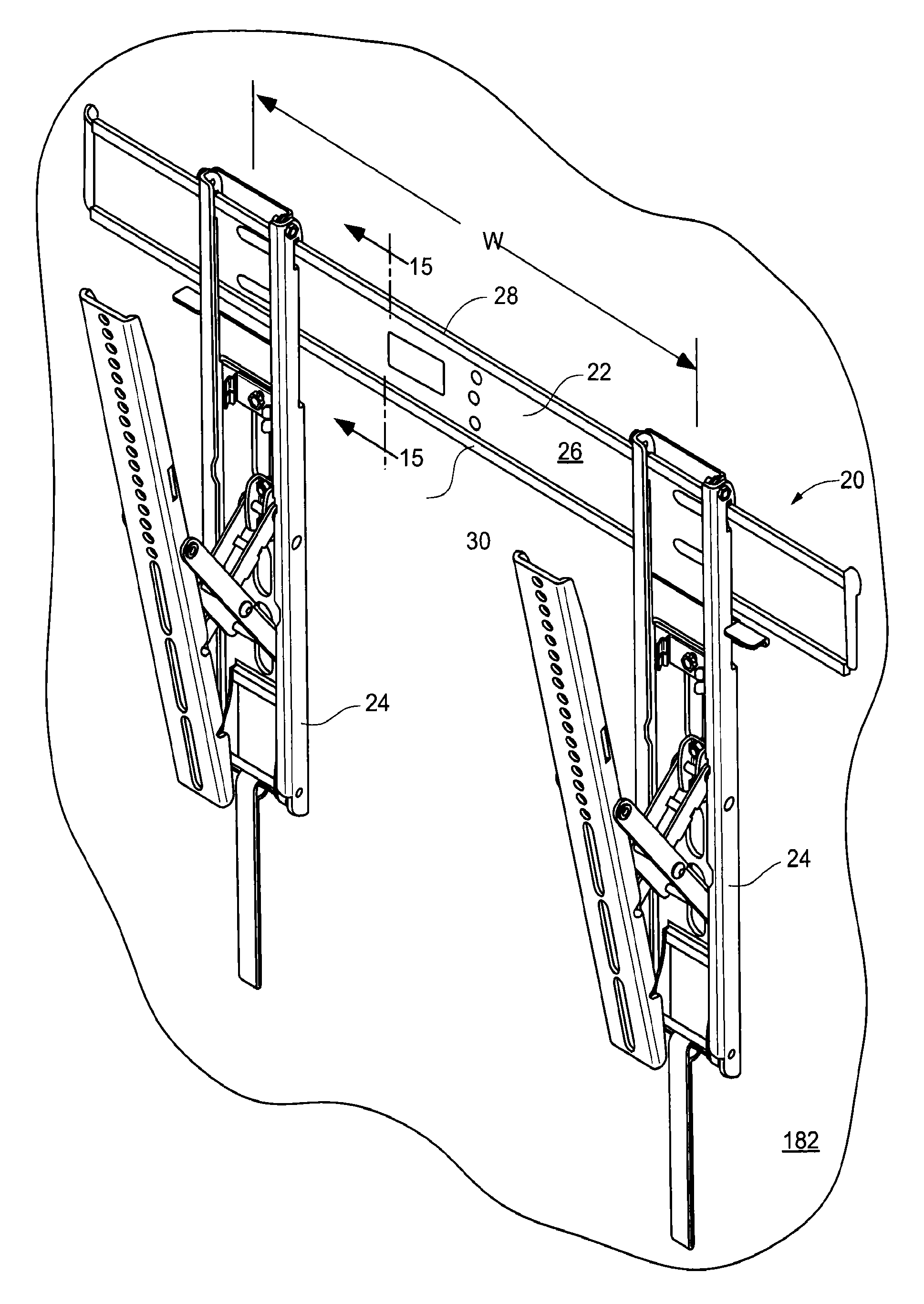
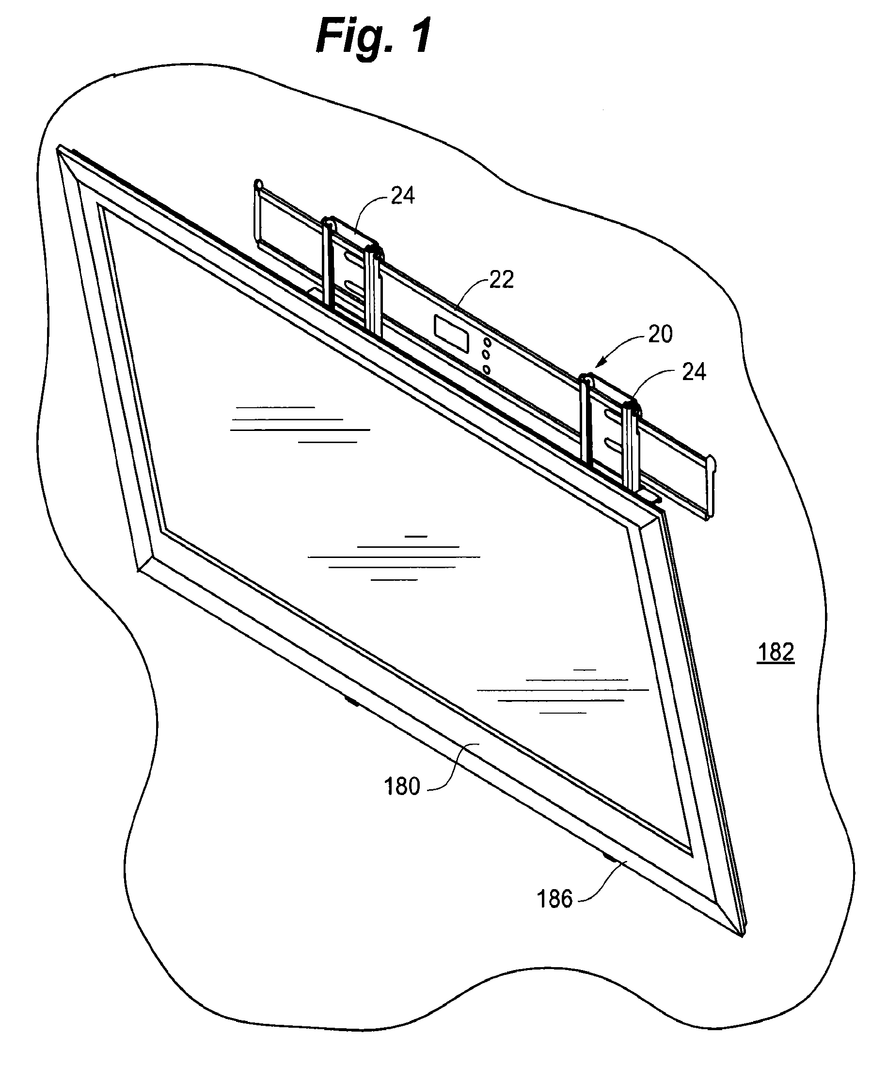
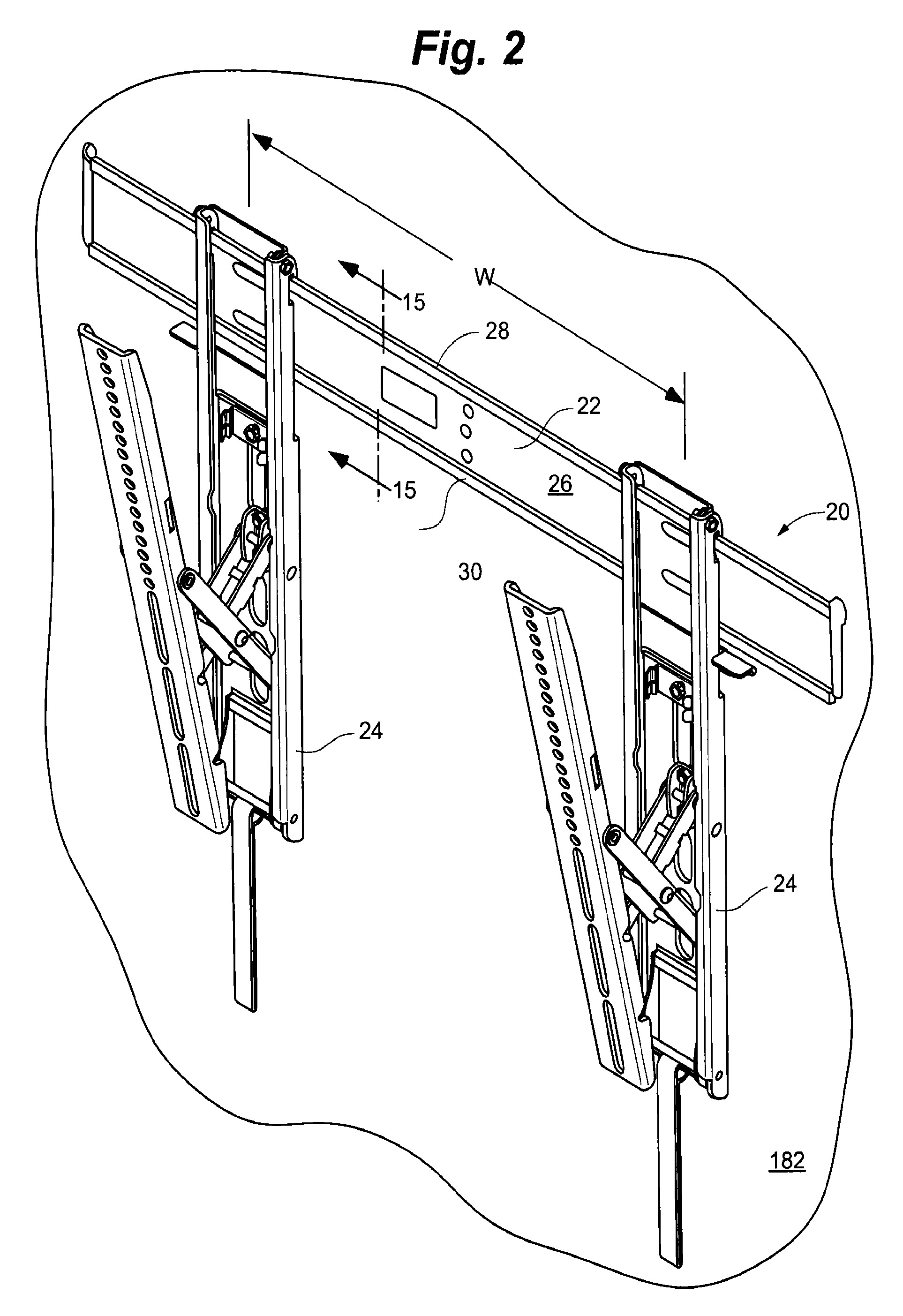
[0038]In an embodiment depicted in FIGS. 1-14, display mount 20 generally includes wall interface plate 22 and tilt assemblies 24. Wall interface plate 22 generally includes planar portion 26 having projecting upper horizontal lip 28 and projecting lower horizontal lip 30. As depicted in the cross-sectional view of FIG. 15, upper lip 28 includes generally horizontal portion 32 extending outwardly from planar portion 26 and vertical portion 34 extending from horizontal portion 32. Lower lip 30 includes generally horizontal portion 36 extending outwardly from planar portion 26 and vertical portion 38 extending from horizontal portion 36.

[0039]Each tilt assembly 24, depicted in exploded view in FIG. 3, generally includes hook bracket 40, latch assembly 42, scissors assembly 44, kickstand assembly 46, and display interface 48. As depicted in FIG. 4, scissors assembly 44 generally includes outer arm assembly 50, inner arm assembly 52, and pivot block 54. Outer arm assembly 50 generally i...


PUM


Abstract

A low-profile mount for a flat panel electronic display that is selectively shiftable between a wall-confronting position wherein the back of the flat panel electronic display is disposed parallel and proximate to the wall surface and a tilt position wherein the top of the display is tilted away from the wall surface. The mount is configured so that points spaced apart forwardly from display receiving surfaces of the mount are shifted along a substantially horizontal axis as the mount is shifted between the wall confronting position and the tilt position. Advantageously, the display can be attached to the mount so that the points are horizontally registered with a center of gravity of the display such that the display is self-balancing at any point along the travel between the wall confronting position and the tilt position.

Description

RELATED APPLICATIONS[0001]The application claims the benefit of U.S. Provisional Application No. 61 / 093,676, entitled LOW PROFILE MOUNT FOR FLAT-PANEL ELECTRONIC DISPLAY, filed Sep. 2, 2008, said application being hereby fully incorporated herein by reference.FIELD OF THE INVENTION[0002]The present invention relates to electronic displays and more specifically to mounts for electronic displays.BACKGROUND OF THE INVENTION[0003]An attribute of modern flat-panel electronic displays that makes them highly desirable to consumers is the aesthetic appeal of a very flat device that has the appearance of a framed photo or painting when hung from a wall. This same attribute is also desirable in that floor and interior space taken up under the display is minimal.[0004]Mounting devices have been developed for flat-panel electronic displays that enable the display to be mounted very close to the wall. These prior mounting devices, however, have drawbacks.[0005]One drawback of prior low-profile m...

Claims


Application Information

Patent Timeline
Patent Type & Authority Patents(United States)
IPC IPC(8): H04N5/64F16M13/02F16M11/10
CPCF16M13/02F16M11/10F16M2200/061
Inventor SMITH, PAUL
Owner LEGRAND AV INC
Why Eureka
Try Eureka