Method and devices for frequency distribution

a frequency distribution and frequency technology, applied in the field of frequency distribution methods and devices, can solve the problems of inability to accurately measure and clock synchronization the path delay, the packet delay is variable, and the clock noise is contributory to the recovery clock. , to achieve the effect of high accuracy synchronization, good synchronization, and high accuracy synchronization

Active Publication Date: 2015-08-18
KHALIFA UNIV OF SCI & TECH +2
View PDF11 Cites 8 Cited by
  • Summary
  • Abstract
  • Description
  • Claims
  • Application Information

AI Technical Summary

Problems solved by technology

The primary challenge in designing a clock distribution system for packet networks is dealing with packet delay variations (PDVs)—that is, the variable packet transit delays.
Packet network devices such as switches and routers introduce a variable delay to packets (PDV) that inhibits accurate path delay measurements and clock synchronization.
Even for techniques that do not require path delay measurements for clock synchronization, the PDV is a direct contributor to the noise in the recovered clock.
The PDV inherent in packet networks is a primary source of clock noise.
The higher the clock noise, the poorer the clock quality rendering the recovered clock sometimes unusable for end system applications when the noise exceeds application defined thresholds.
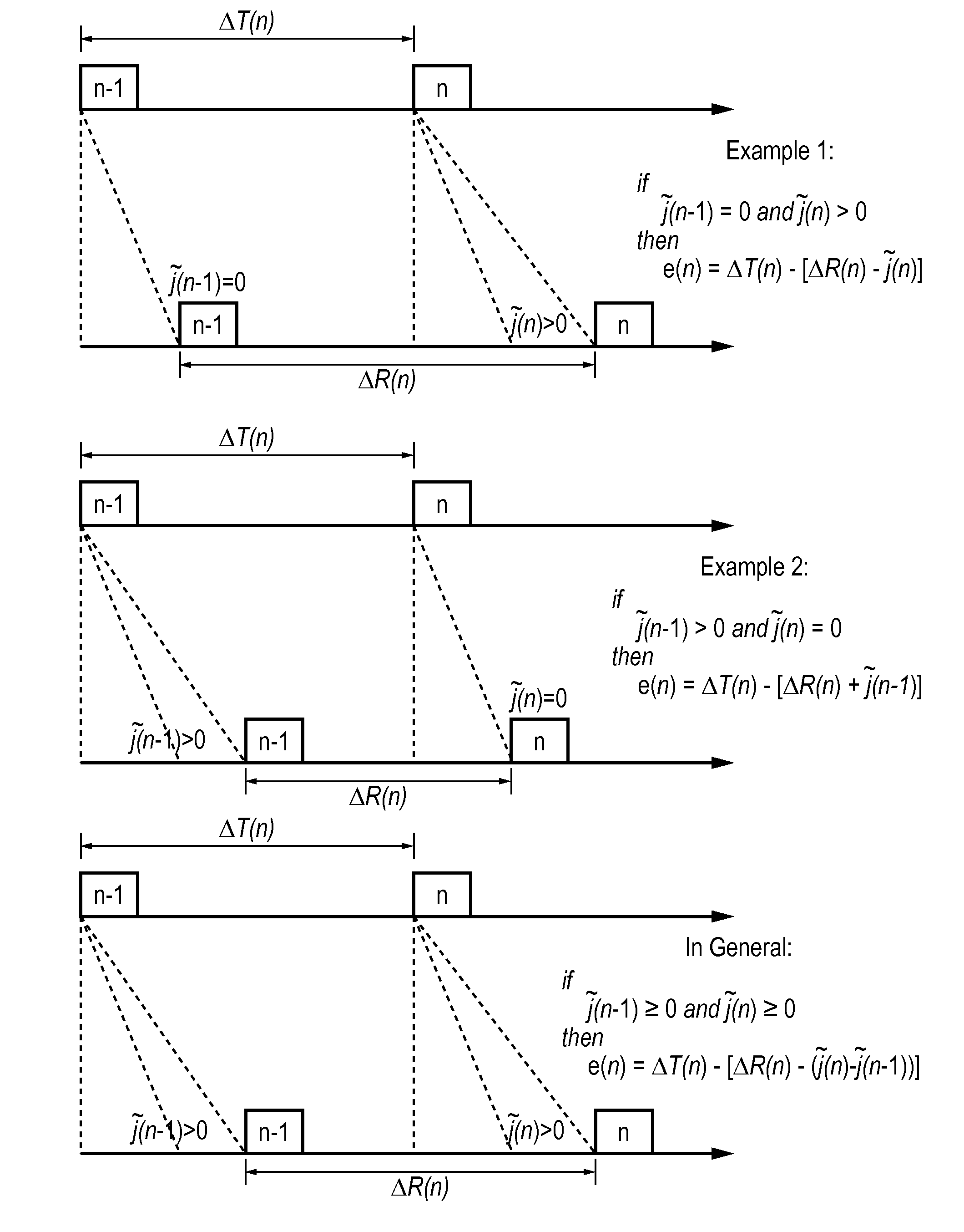
For instance, for time synchronization, the variation in delay from packet to packet through the network induces noise in the slave's perception of the time at the master.
Constant delay would cause a fixed offset, however variable delay causes a varying estimate of the offset.
However, switched networks do not necessarily have symmetrical communication paths, due to the buffering process in the network nodes, which can result in asymmetrical packet delay times. To address this, PTP provides a method, using transparent clock devices (implemented in switches and routers), to measure and account for the delay experienced by PTP messages in a time interval field in the PTP messages.
The variations in these delays means that the assumption that packet delay is the same in each direction is invalid, thus rendering the path delay calculations of PTP inaccurate.
E2E transparent clocks do not provide correction for the propagation delay of the link itself between devices.
As each BC recovers the clock and regenerates a new timing signal, this can lead to the introduction of clock wander (low frequency jitter i.e., jitter below 10 Hz).
If a chain of BCs are used, like any chain of equipment where the clock is recovered and regenerated in each piece of equipment, then it is expected that there will be some accumulation of wander along the chain in the transferred clock frequency.
TCs cannot be combined with non-PTP devices in a synchronization path between a master and a slave clock.
Depending on implementation, the internal queuing structure of the TC device may not allow an accurate calculation and update of the residence time in the correction field of a PTP message (see full discussion later).
When E2E TCs are used, there can be scalability issues for slaves that implement the path delay mechanism.
A master will have to handle all slaves that implement the delay mechanism making scalability a problem if there many slaves.
Almost all of the above disadvantages related to how the TC is implemented.
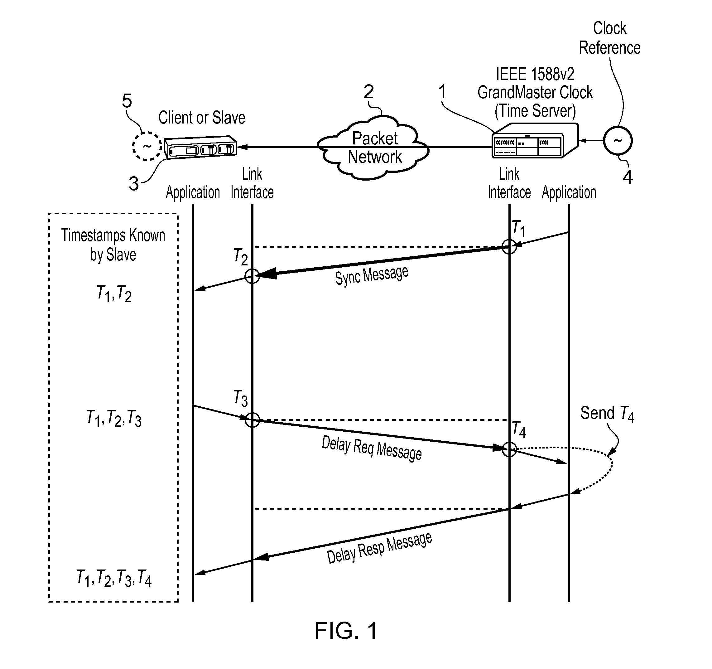
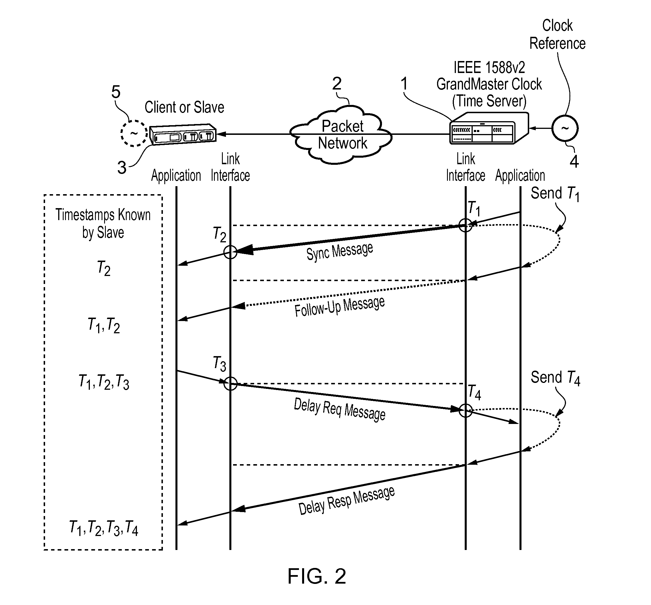
Compared to the other methods, clock recovery here is more challenging because the slave 3 is exposed to all the PDV generated by the intermediate packet network 2.
The drawback, however, in doing this is that the very low-pass PLL leads to a high-pass characteristic where the loop allows more local oscillator noise to pass through to the clock output.
The greater the PDV, the more difficult it is to maintain synchronization between master and slave.
There are no current guidelines on how this can be done correctly.

Method used


Image

  • Method and devices for frequency distribution
  • Method and devices for frequency distribution
  • Method and devices for frequency distribution

Examples


Embodiment Construction

[0132]Accordingly, at their broadest, methods of the present invention provide for synchronising the frequency of an oscillator in a slave device to the frequency of a master clock in a master device by taking account of delay variations to messages between them.

[0133]A first aspect of the present invention provides a method of synchronising the frequency of an oscillator in a slave device to the frequency of a master clock in a master device, the method including the steps of:

[0134]a) receiving in the slave device a first message from said master device having a first time-stamp which is a time-stamp of said master clock indicating the precise time of sending of said first message and a first correction value which is the cumulative delay encountered by the message during its passage from the master device to the slave device;

[0135]b) extracting said time-stamp and said correction value from said first message and recording a first value of a counter in the slave device at the time...


PUM


Abstract

This invention relates to methods and devices for frequency distribution based on, for example, the IEEE 1588 Precision Time Protocol (PTP). Packet delay variation (PDV) is a direct contributor to the noise in the recovered clock and various techniques have been proposed to mitigate its effects. Embodiments of the invention provide a mechanism to directly measure and remove PDV effects in the clock recovery mechanism at a slave clock. One particular embodiment provides a clock recovery mechanism including a phase-locked loop (PLL) with a PDV compensation feature built-in. An aim of the invention is to enable a slave clock to recover the master clock to a higher quality as if the communication path between master and slave is free of PDV. This technique may allow a packet network to provide clock synchronization services to the same level as time division multiplexing (TDM) networks and Global Positioning System (GPS).

Description

FIELD OF THE INVENTION[0001]The present invention relates to methods and devices for frequency distribution. It is particularly, but not exclusively, concerned with providing a mechanism to directly measure and remove packet delay variation effects in the clock recovery mechanism at a slave clock.BACKGROUND OF THE INVENTION[0002]IEEE 1588 Precision Time Protocol (“PTP”) is defined in the IEEE 1588-2002 (Version 1) and 1588-2008 (Version 2) standards. IEEE 1588 has been designed as an improvement to current methods of synchronization within a distributed network of devices. It is designed for systems requiring very high accuracies beyond those attainable using Network Time Protocol (NTP). Unlike NTP, IEEE 1588 uses ‘hardware timestamping’ approach to deliver timing accuracy well under a microsecond. It is also designed for applications that cannot bear the cost of a GPS receiver at each node, or for which GPS signals are inaccessible.[0003]IEEE 1588 is now the industry accepted packe...

Claims


Application Information

Patent Timeline
Patent Type & Authority Patents(United States)
IPC IPC(8): H04J3/06
CPCH04J3/0682H04J3/0664H04J3/0697H04J3/0673H04J3/0667
Inventor AWEYA, JAMESAL SINDI, NAYEFAL-ZUBAIDI, SAEED
Owner KHALIFA UNIV OF SCI & TECH
Why Eureka
Try Eureka