Electrical junction box

a junction box and electric technology, applied in the field of electric junction boxes, can solve the problems of large bend radius, large time and effort required to perform routing, and thick wires for input power sources connected to batteries, alternators, etc., and achieve the reduction of the distance by which each wire protrudes from the box body, the effect of reducing the overlap of wires and reducing the bend radius

Active Publication Date: 2015-09-29
SUMITOMO WIRING SYST LTD
View PDF13 Cites 4 Cited by
  • Summary
  • Abstract
  • Description
  • Claims
  • Application Information

AI Technical Summary

Benefits of technology

[0008]The invention relates to an electrical junction box that has a fuse module with fuse attachment portions that open into a first side face of a box body. The fuse attachment portions are arranged side by side in a plurality of tiers one above another. Connector attachment portions open into a second side face of the box body that is perpendicular to the first side face have input terminals of the fuse module. The connector attachment portions in the second side face are disposed in mutually shifted positions in a direction in which the tiers of fuse attachment portions are placed one above another. Thus, overlapping of the wires can be reduced even if a plurality of wires extending from connectors attached to the connector attachment portions are bent in the same direction. Therefore, the bend radius of the wires extending from the connectors can be smaller and the distance by which each wire protrudes from the box body can be reduced, so that the layout space of the electrical junction box including the wires can be reduced. In addition, it is possible to dispose the plurality of connector attachment portions in positions that are shifted in the vertical direction without leading to an increase in the dimension of the electrical junction box in the vertical direction by efficiently using the height of the fuse module in the vertical direction in which the tiers of the fuse attachment portions are placed one above another.
[0009]The connector attachment portions may partially overlap in the vertical direction, but preferably are disposed at a distance from each other in the vertical direction without overlapping. In this manner, overlapping of the wires can be avoided more effectively when the wires extending from the connector attachment portions are bent, and the bend radius of each wire can be reduced even more. Thus, the dimensions of the electrical junction box, including the wires, can be decreased even more.
[0010]The connector attachment portions preferably are spaced from each other in the direction in which the tiers of the fuse attachment portions are placed one above another. Thus, the connector attachment portions are shifted in a direction in which the second side face extends. L-shaped connectors are connected to at least the connector attachment portions that are on the innermost side of the box body in the direction in which the second side face extends. Thus, a vacant space with no connector attachment portions is formed next to at least the connector attachment portion that on the innermost side in the direction in which the second side face extends. The L-shaped connectors use this vacant space to suppress the protruding distance of the L-shaped connector from the box body. Furthermore, the L-shaped connector enables the direction in which the wire extends to be changed without bending the wire, thereby further reducing the distance by which the wire protrudes from the box body. Moreover, the non-overlapping disposition of the connector attachment portions as seen in the direction in which the tiers of the fuse attachment portions are placed one above another, enables the attachment state of the connectors to the respective connector attachment portions to be checked visually from above.

Problems solved by technology

The wires overlap each other, and much time and effort is required to perform routing.
Wires for input power sources that are connected to batteries, alternators, and the like are often thick and require a large bend radius.

Method used


Image

  • Electrical junction box
  • Electrical junction box
  • Electrical junction box

Examples


Embodiment Construction

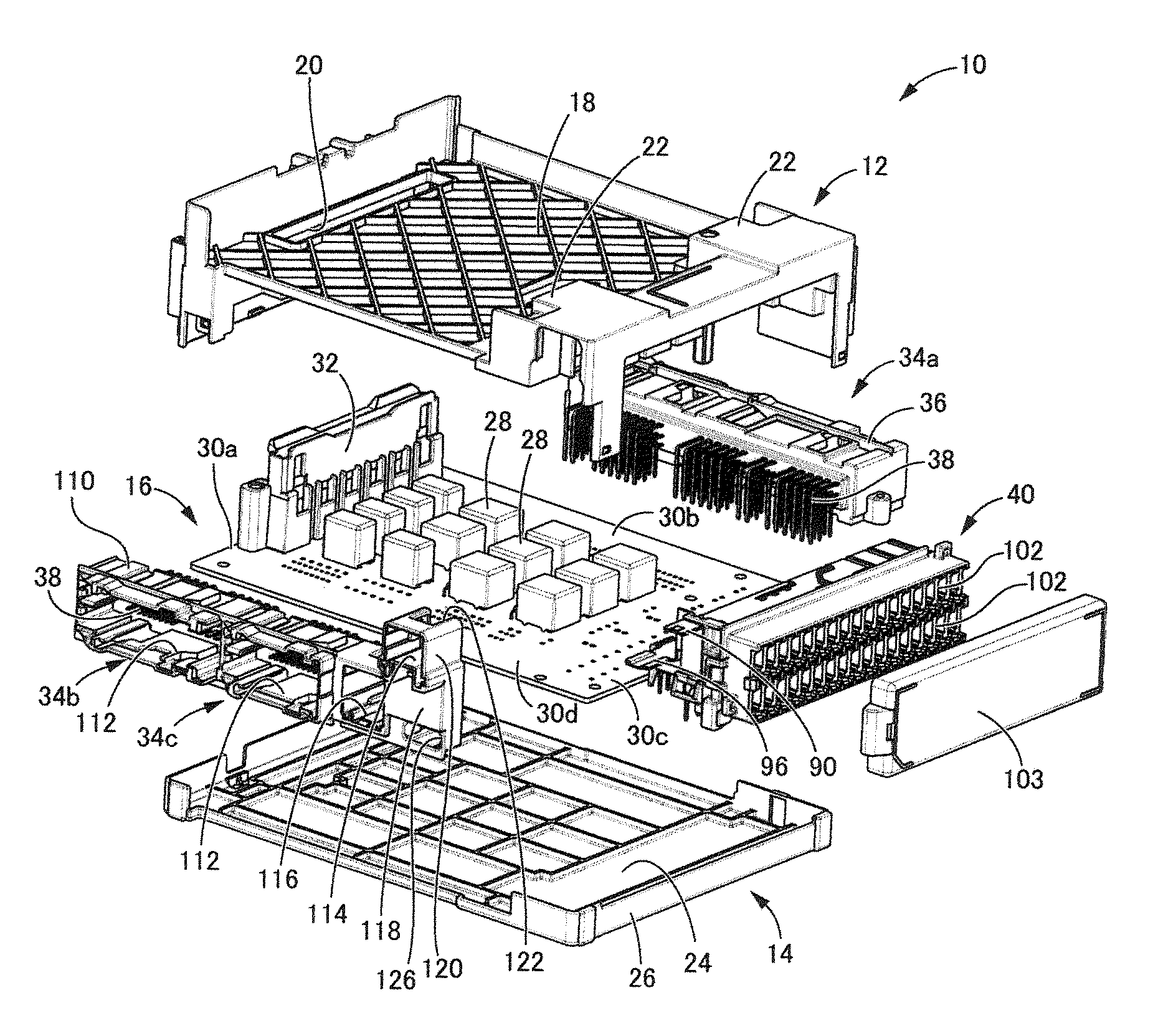
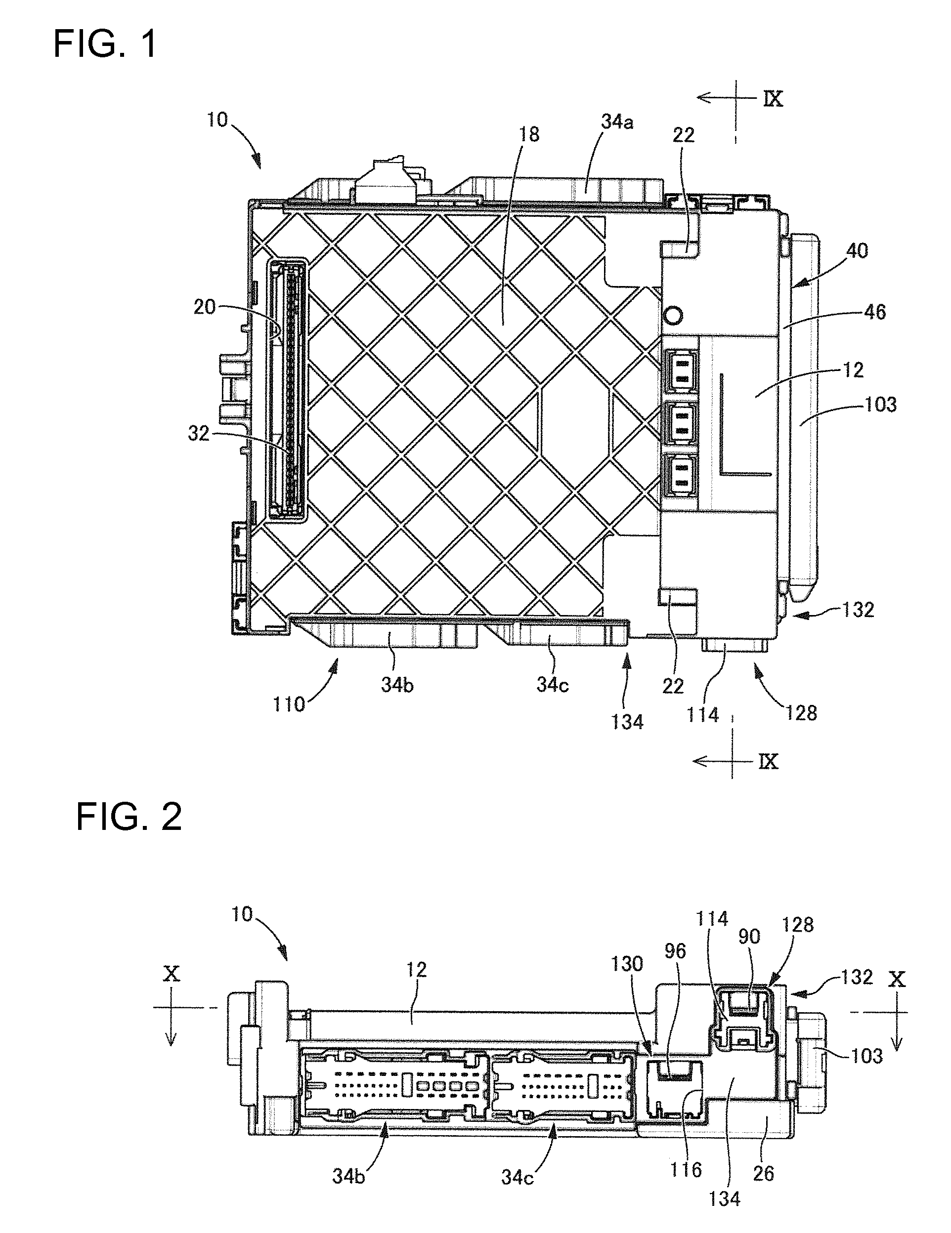
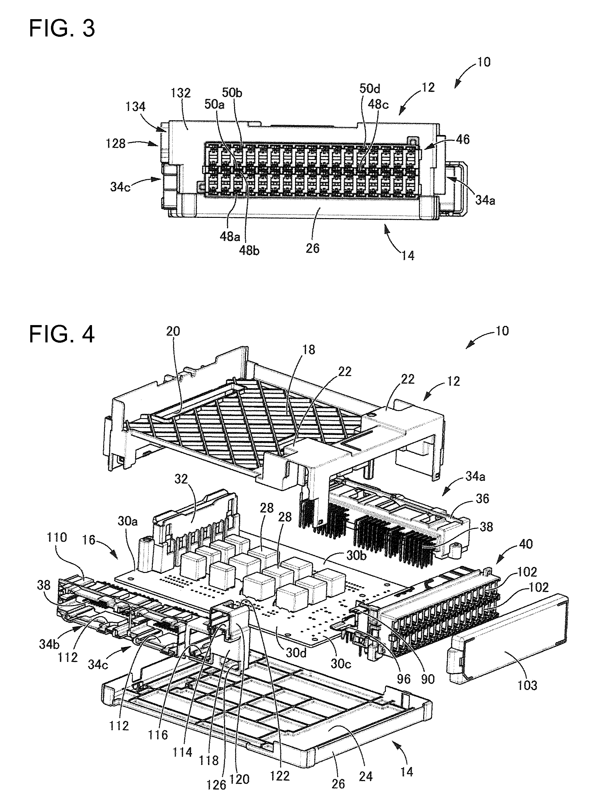
[0027]FIGS. 1 to 4 show an electrical junction box 10 in accordance with the invention. As is clear from FIG. 4, the electrical junction box 10 has a printed circuit board 16 that constitutes an internal circuit accommodated between an upper case 12 and a lower case 14. In the following description, “upper side” refers to the upper side in FIG. 2, and “lower side” refers to the lower side in FIG. 2.

[0028]The upper case 12 is molded unitarily of synthetic resin and has a substantially rectangular box-like shape that opens down. An attachment surface 18 is formed at an upper face of the upper case 12, and a connector insertion hole 20 penetrates the attachment surface 18 at one end of the upper case 12. Bearings 22 are provided outside the attachment surface 18 on the side opposite the connector insertion hole 20.

[0029]The lower case 14 is molded unitarily of synthetic resin and has a substantially rectangular box-like shape that opens up. The lower case 14 includes a bottom wall 24 w...


PUM


Abstract

An electrical junction box has a fuse module (40) with a plurality of fuse attachment portions (102) open into a first side face (132) and arranged side by side in a plurality of tiers that are placed one above another. A plurality of connector attachment portions (128) and (130) in which respective input terminals (90) and (96) of the fuse module (40) are disposed are provided so as to open into a second side face (134) that is perpendicular to the first side face (132), and are disposed in mutually shifted positions in a direction in which the tiers of the fuse attachment portions (102) are placed one above another.

Description

BACKGROUND[0001]1. Field of the Invention[0002]The invention relates to an electrical junction box for an automobile or the like, and particularly relates to an electrical junction box in which a plurality of connector attachment portions to be connected to respective connectors open to a lateral side of a box body.[0003]2. Description of the Related Art[0004]Electrical junction boxes, such as junction boxes in automobiles and the like, are equipped with a large number of fuse attachment portions to which fuses are attached for preventing an overcurrent from flowing to various electrical components. JP 2008-53079A discloses an electrical junction box equipped with a fuse module in which fuse attachment portions open into a side face of a box body and are arranged side by side in a plurality of tiers placed one above another to enable a large number of fuses to be connected with high space efficiency. A connector attachment portion is open into a side face of the box body and is conn...

Claims


Application Information

Patent Timeline
Patent Type & Authority Patents(United States)
IPC IPC(8): H05K5/00B60R16/023H01H85/20
CPCH05K5/0004B60R16/0238H01H2085/208H01H2085/2075
Inventor HATTORI, YUUICHIODA, AKIHIRO
Owner SUMITOMO WIRING SYST LTD
Why Eureka
Try Eureka