
Electrical junction box
a junction box and electric technology, applied in the field of electric junction boxes, can solve the problems of large bend radius, large time and effort required to perform routing, and thick wires for input power sources connected to batteries, alternators, etc., and achieve the reduction of the distance by which each wire protrudes from the box body, the effect of reducing the overlap of wires and reducing the bend radius
- Summary
- Abstract
- Description
- Claims
- Application Information
AI Technical Summary
Benefits of technology
Problems solved by technology
Method used
Image

Examples
Embodiment Construction
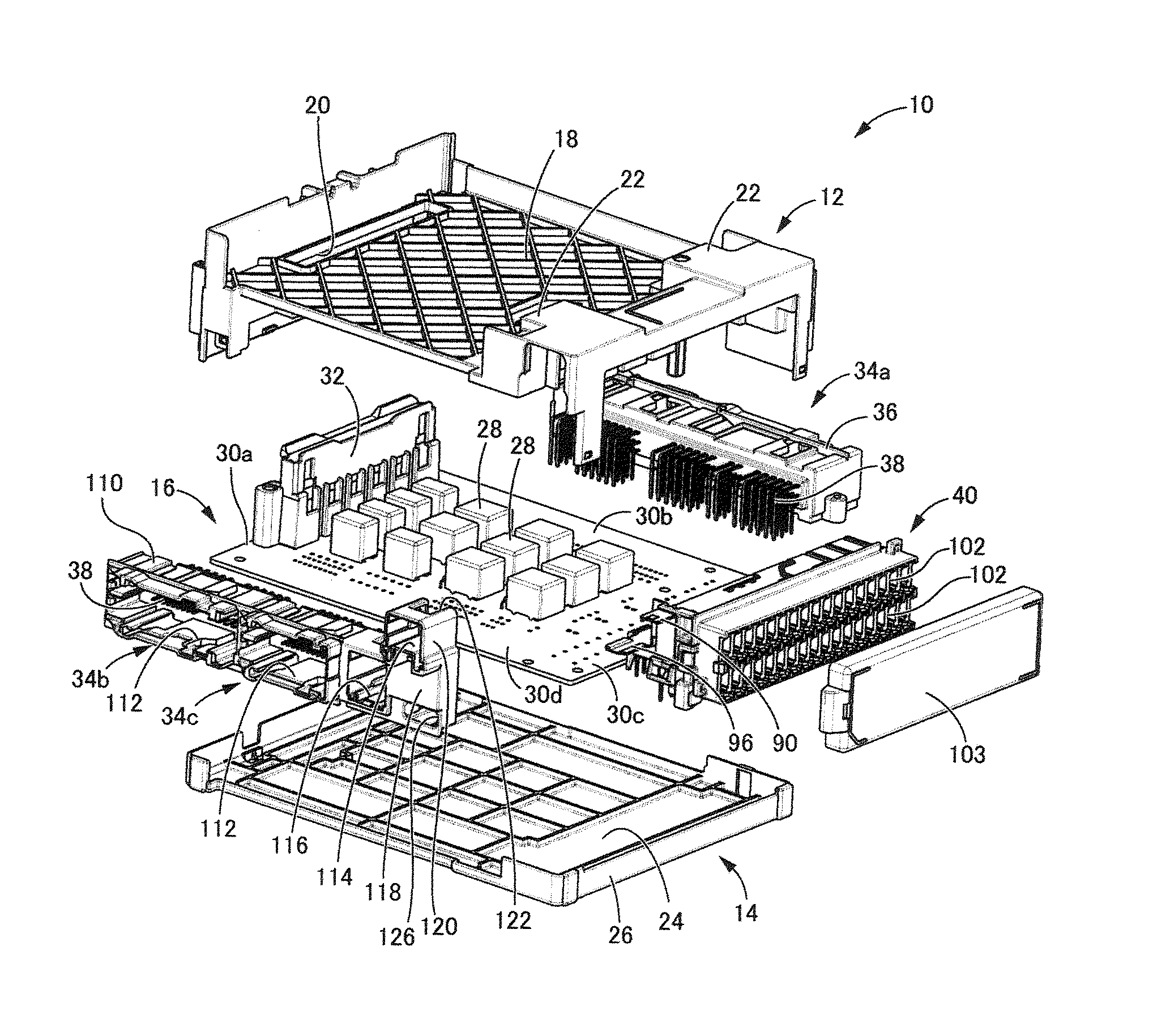
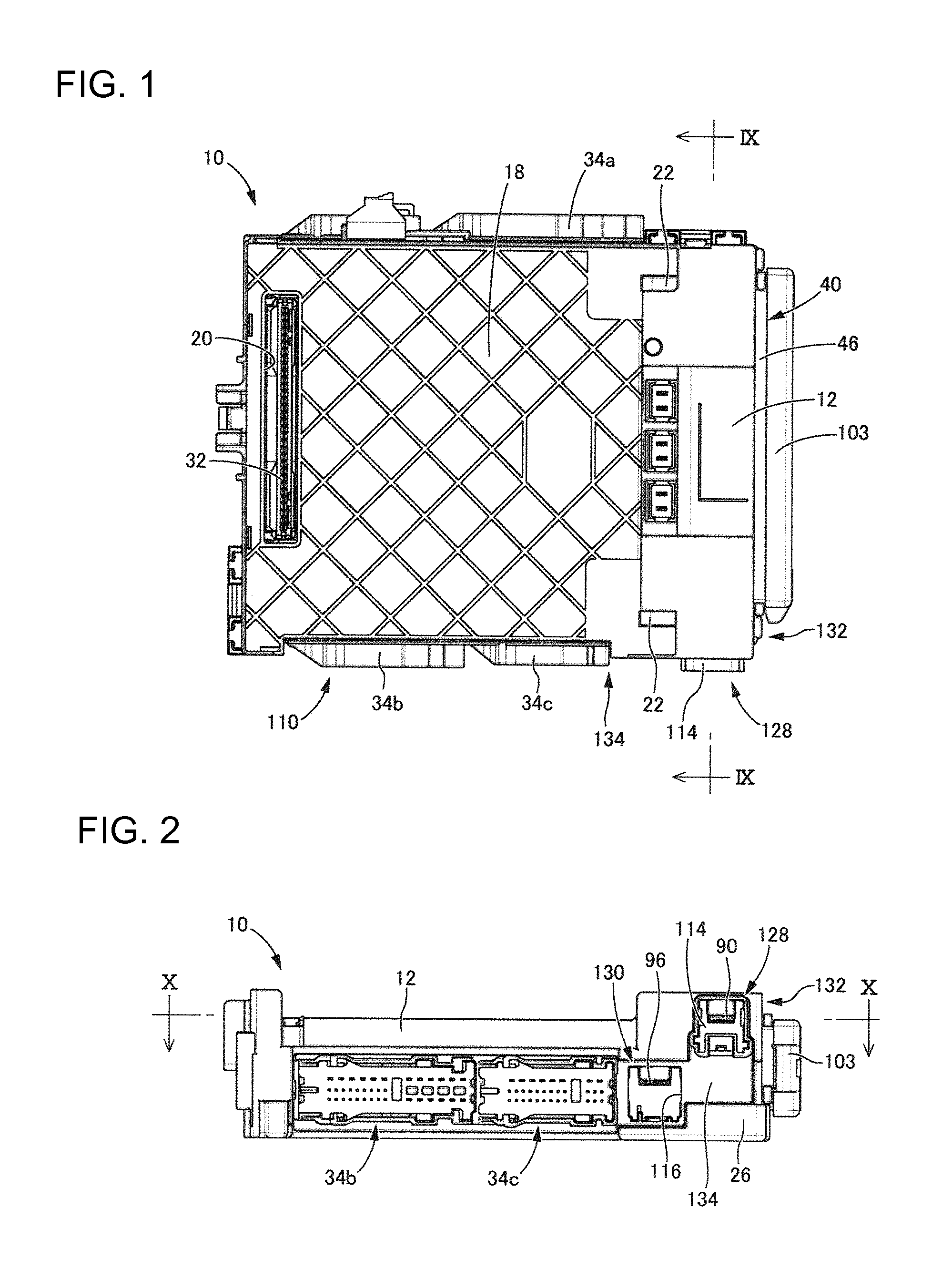
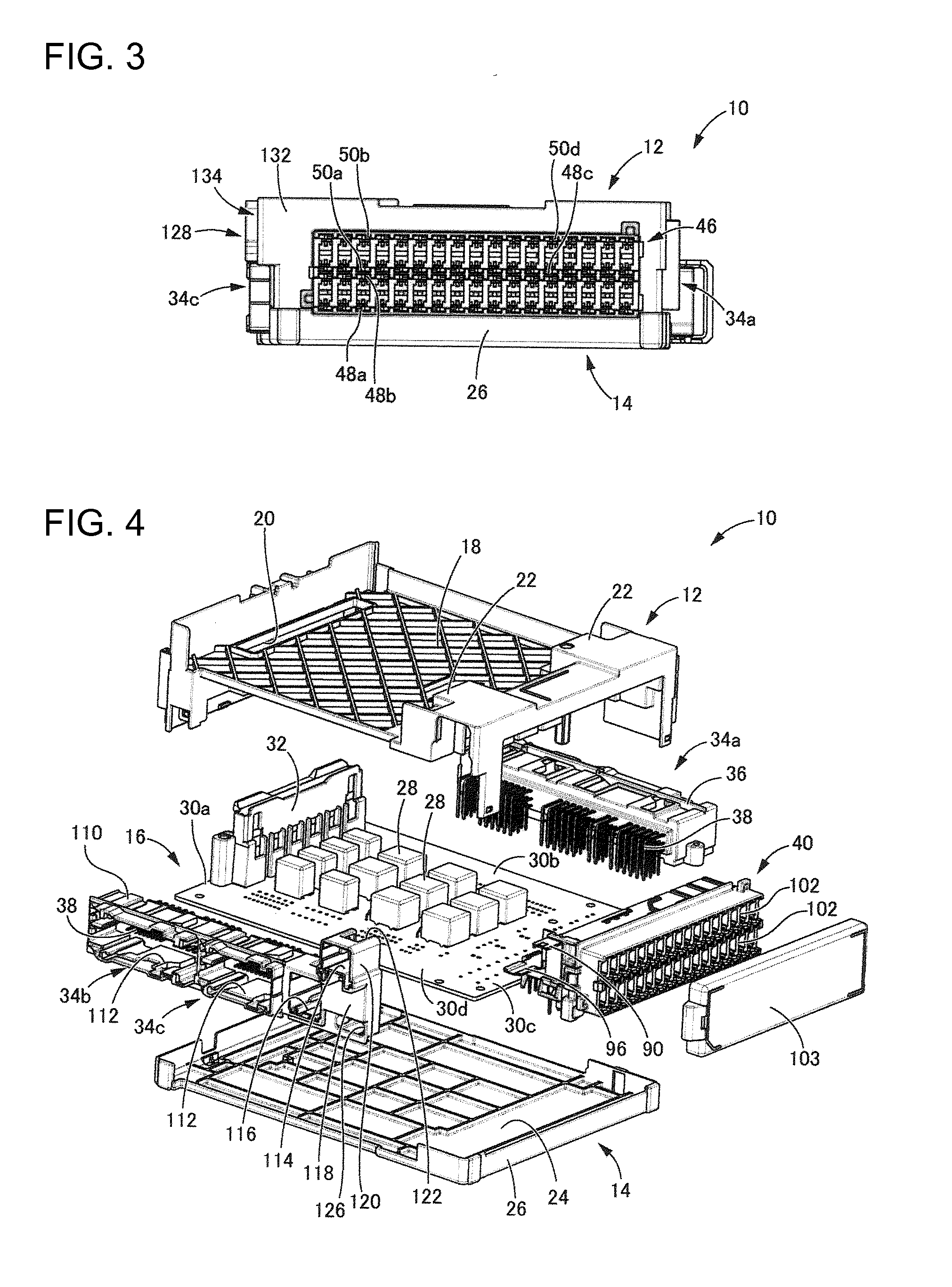
[0027]FIGS. 1 to 4 show an electrical junction box 10 in accordance with the invention. As is clear from FIG. 4, the electrical junction box 10 has a printed circuit board 16 that constitutes an internal circuit accommodated between an upper case 12 and a lower case 14. In the following description, “upper side” refers to the upper side in FIG. 2, and “lower side” refers to the lower side in FIG. 2.
[0028]The upper case 12 is molded unitarily of synthetic resin and has a substantially rectangular box-like shape that opens down. An attachment surface 18 is formed at an upper face of the upper case 12, and a connector insertion hole 20 penetrates the attachment surface 18 at one end of the upper case 12. Bearings 22 are provided outside the attachment surface 18 on the side opposite the connector insertion hole 20.
[0029]The lower case 14 is molded unitarily of synthetic resin and has a substantially rectangular box-like shape that opens up. The lower case 14 includes a bottom wall 24 w...
PUM
 Abstract
Description
Claims
Application Information