Mirror adapter mount

a technology of mirror adapter and mount, which is applied in the direction of machine supports, bicycle equipment, other domestic objects, etc., can solve the problems of motorcycling manufacturers leaving little or no real estate on the handlebars

Active Publication Date: 2015-11-10
CARNEVALI JEFFREY D
View PDF20 Cites 16 Cited by
  • Summary
  • Abstract
  • Description
  • Claims
  • Application Information

AI Technical Summary

Problems solved by technology

However, motorcycle manufacturers leave little or no real estate on the handlebars for the mounting of after-market accessories.

Method used


Image

  • Mirror adapter mount
  • Mirror adapter mount
  • Mirror adapter mount

Examples


Embodiment Construction

[0020]In the Figures, like numerals indicate like elements.

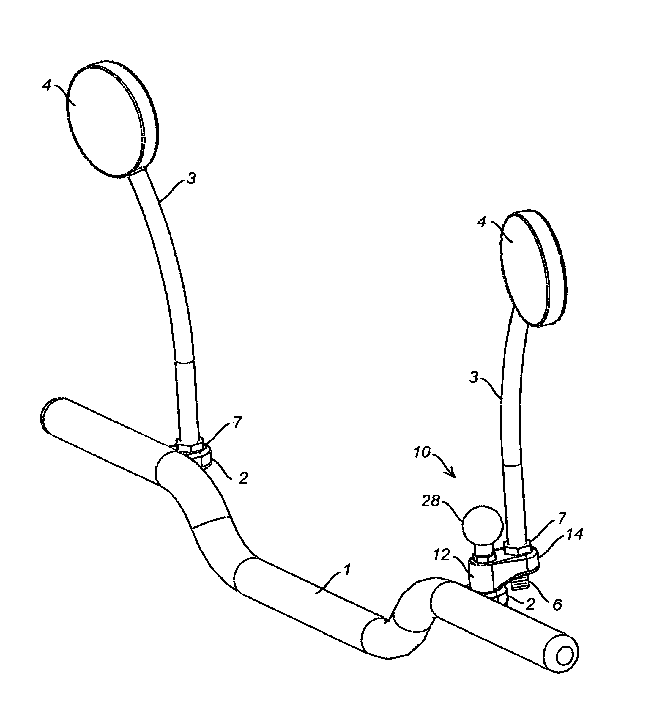
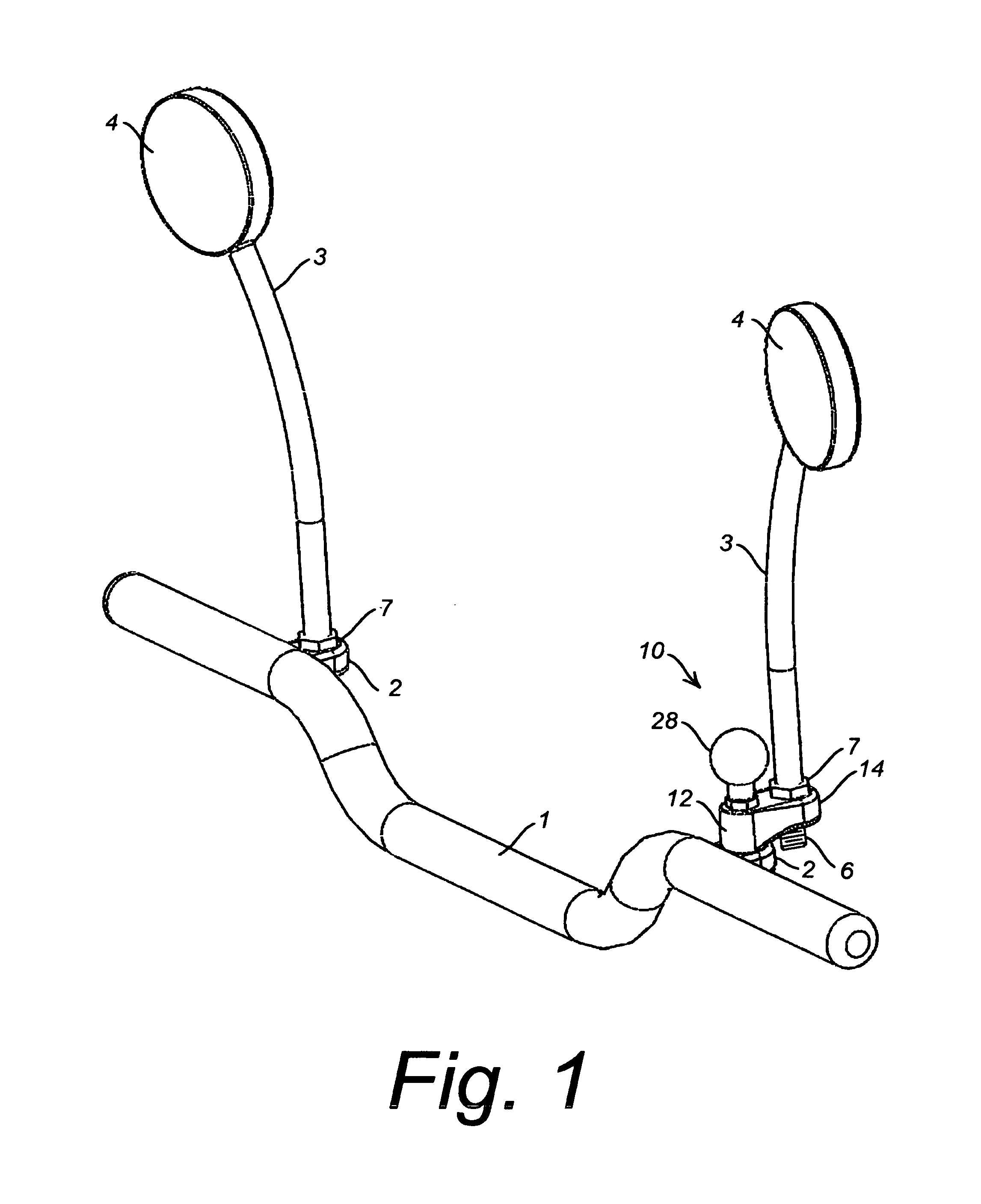
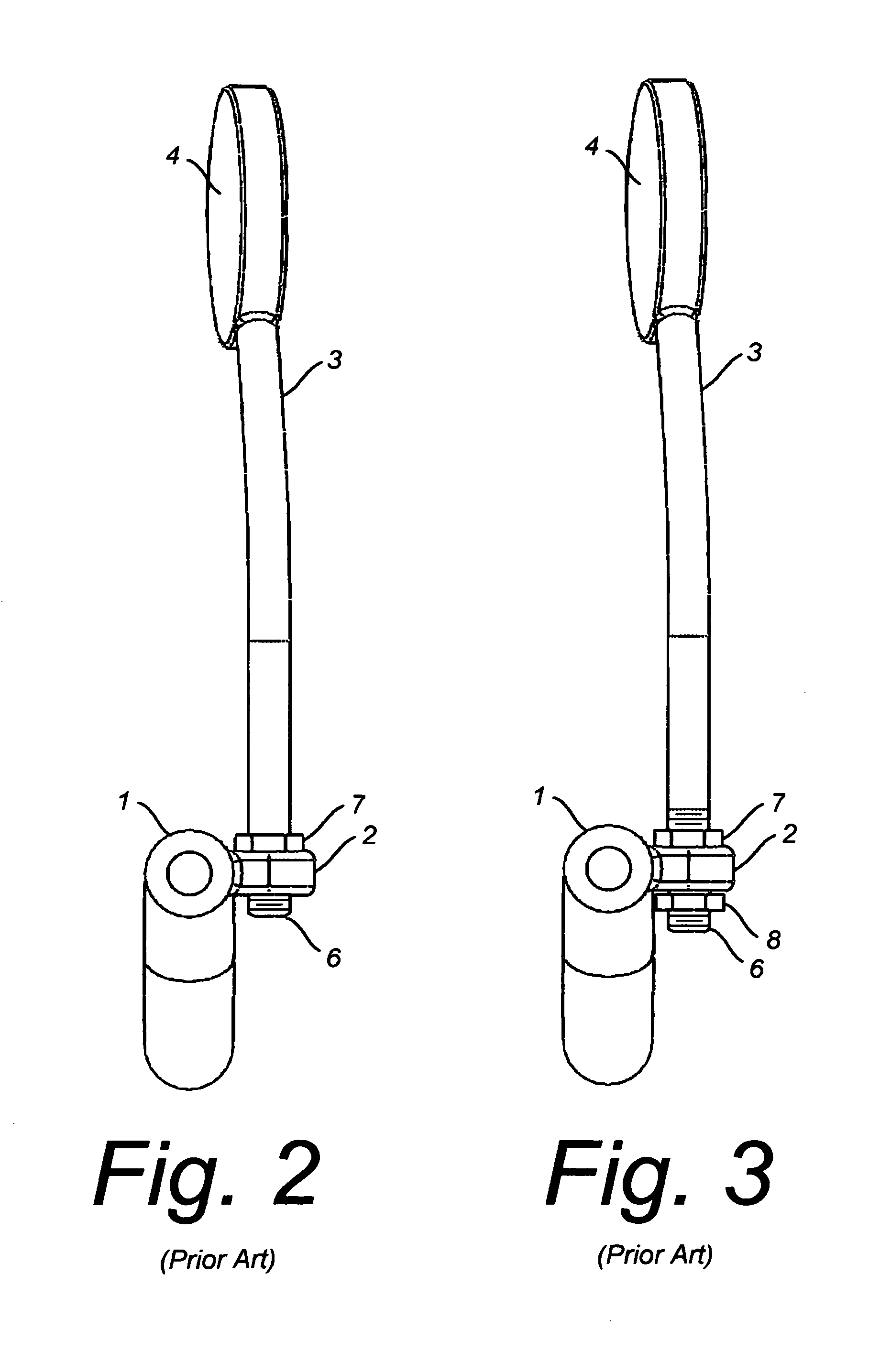
[0021]FIG. 1 illustrates a handlebar 1 having a pair of mirror mount receivers 2 each formed as an eye sized to receive therethrough a mirror mounting stem 3 supporting a rear view mirror 4. As illustrated in FIG. 4, mirror mount receiver eye 2 is formed with an aperture 5 sized to receive mounting stem 3 supporting mirror 4. For example, aperture 5 is threaded to mate with a thread 6 formed on mounting stem 3 supporting mirror 4. As more clearly shown in FIG. 2, mirror mounting stem 3 may include a wrench interface 7, such as a hex, for tightening mounting stem 3 with mirror mount receiver eye 2. Alternatively, as illustrated in FIG. 3, instead of a matching thread, aperture 5 of mirror mount receiver eye 2 is a clearance hole for thread 6 of mirror mounting stem 3, and a nut 8 engages thread 6 on mounting stem 3 opposite from wrench interface 7. Also, wrench interface 7 may be replaced by a nut 9 that engages thread 6 abov...


PUM


Abstract

A novel mirror adapter mount for mounting between a handlebar mirror mount and a mirror normally secured thereto. According to one embodiment, the mirror adapter mount having a substantially rigid bracket with a first and second spaced-apart apertures each structured to receive a threaded shaft of the mirror, a threaded coupler having a shaft having a threaded portion thereof that is sized to be received through the first aperture in the bracket; a first securing means for securing the threaded portion of the shaft of the coupler to the handlebar mirror mount with a portion of the bracket secured there between; and a second securing means for securing the threaded shaft of the mirror to the second aperture of the bracket.

Description

FIELD OF THE INVENTION[0001]The present invention relates generally to means for providing mounting space on motorcycle handlebars, and in particular means for expanding pre-existing mounting space.BACKGROUND OF THE INVENTION[0002]Many after-market accessories are available for mounting on the handlebars of motorcycles. However, motorcycle manufacturers leave little or no real estate on the handlebars for the mounting of after-market accessories. Therefore, innovative ways of maximizing utilization of the available real estate are required.SUMMARY OF THE INVENTION[0003]The present invention is a novel mounting device, formed of a pivot connector having a connector base and a coupler interface with a pivot joint therebetween; a means for adjusting a rotational stiffness of the pivot joint; a ball component formed on the coupler interface opposite from the pivot joint; and a coupler adapted for securing the connector base to a mirror mount of a handlebar.[0004]According to one aspect ...

Claims


Application Information

Patent Timeline
Patent Type & Authority Patents(United States)
IPC IPC(8): B60R1/06B62J29/00B60R1/02
CPCB62J29/00B60R1/02B60R1/06
Inventor CARNEVALI, JEFFREY D.
Owner CARNEVALI JEFFREY D
Why Eureka
Try Eureka