One-piece hinge body and hinge assembly for pivoting elements

a one-piece, hinge technology, applied in the direction of hinges, wing accessories, rod connections, etc., can solve the problems of increasing the outer dimensions of the hinge and therefore of the roll container, causing strain to the hinge, and the hinge body is known to be prone to fail in everyday use, so as to achieve the effect of withstanding traction

Active Publication Date: 2015-11-10
K HARTWALL OY AB
View PDF22 Cites 2 Cited by
  • Summary
  • Abstract
  • Description
  • Claims
  • Application Information

AI Technical Summary

Benefits of technology

[0007]Considerable benefits are gained with aid of the present invention. The novel construction of the hinge body is optimized for withstanding the strain caused by handling maneuvers which most commonly lead to a failing hinge. Specifically, by having the terminal ends of the body mate at the inner portion of the hinge body, the point of discontinuity is on the inner side of the joint, whereby the surface on the outside of the joint is solid. By having a solid outer hinge body surface, the hinge body is more suitable to withstand traction caused by forcing the door to close on items not quite fitting inside the roll container.

Problems solved by technology

However, said closing extension of the hinge body increases the outer dimensions of the hinge and therefore of the roll container.
This problem could be solved with a multi-piece hinge body, as disclosed in EP 1353030 A2, but such hinge bodies are known to be prone to fail in everyday use when attempting to close the door of a roll container which has been loaded to the brimful.
Most common failures are due to damages caused by closing the door of a full roll container, whereby outwardly protruding content of the container induces strain to the hinge during closing movement of the door.

Method used


Image

  • One-piece hinge body and hinge assembly for pivoting elements
  • One-piece hinge body and hinge assembly for pivoting elements
  • One-piece hinge body and hinge assembly for pivoting elements

Examples


Embodiment Construction

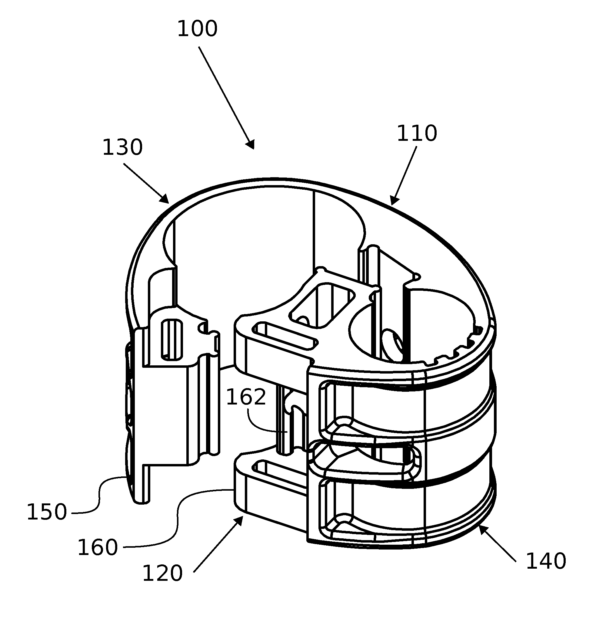
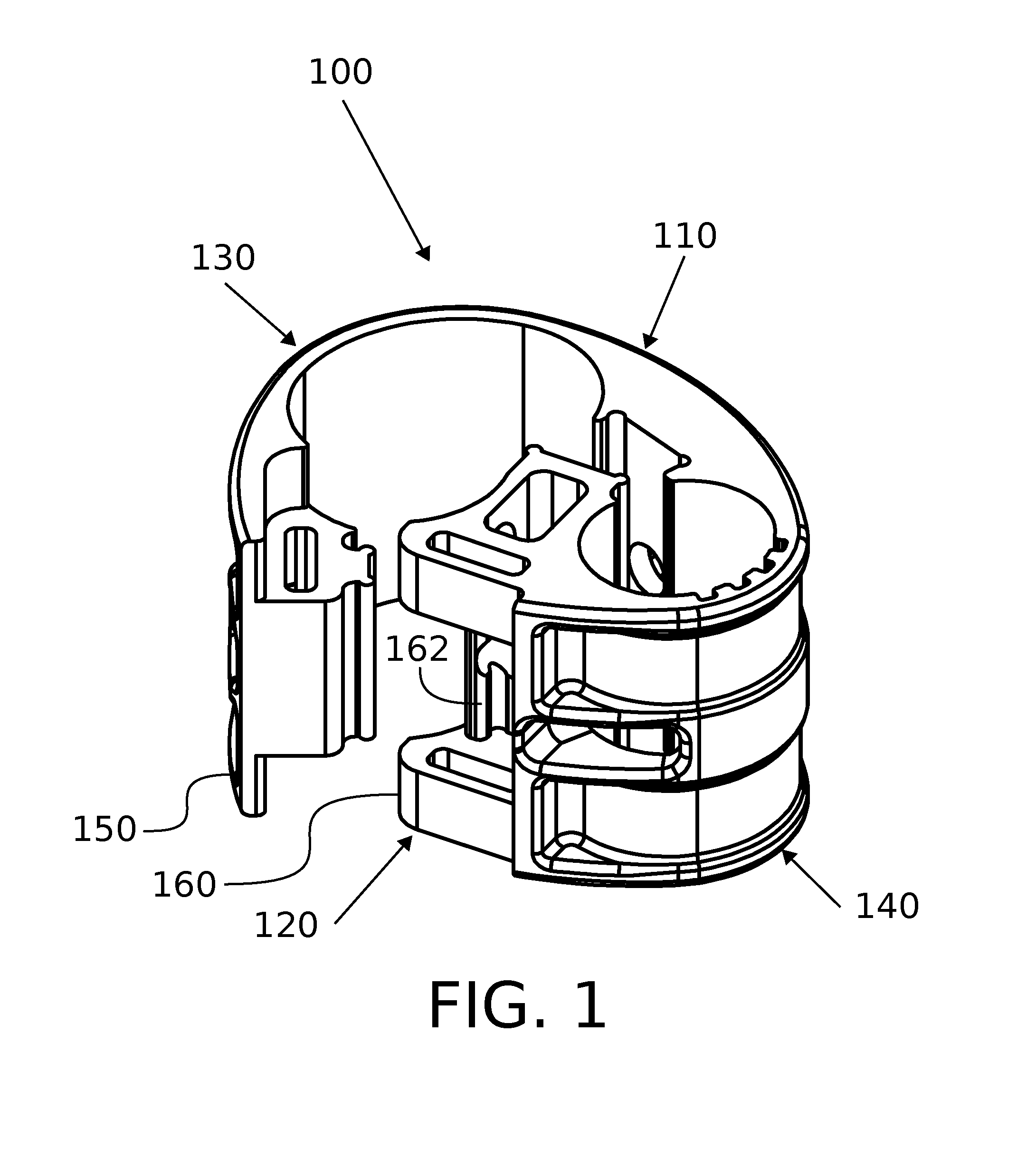
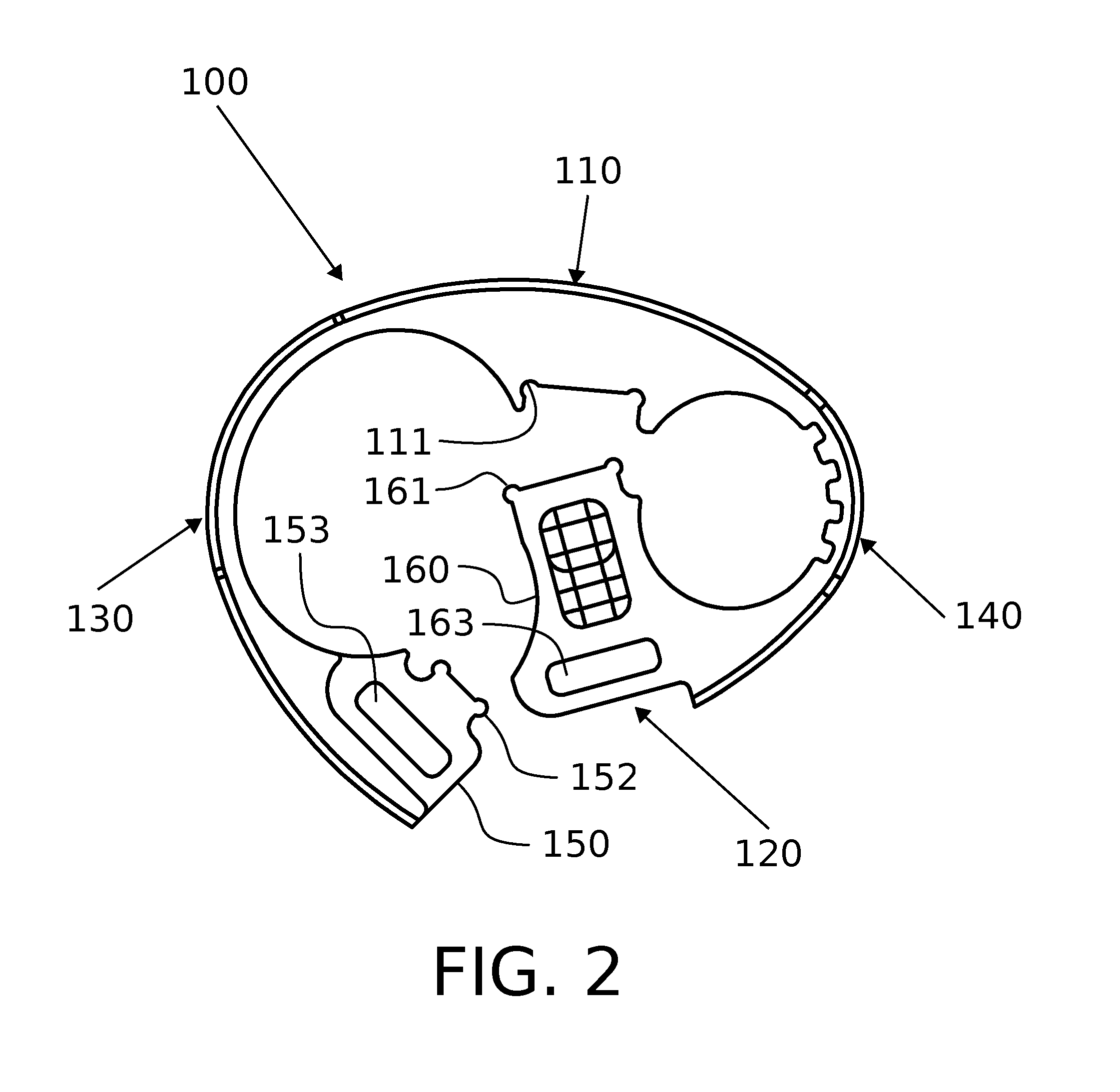
[0016]As illustrated in FIGS. 1 to 5 and according to a disclosed exemplary embodiment, a one-piece hinge body 100 is provided such that the hinge body 100 may be opened for receiving the profiles 300, 400 to be pivoted. The hinge body 100 is made from a material that can be molded into an appropriate form, which is later described, and which material is flexible enough to allow the hinge body 100 to be opened according to FIG. 1. Suitable flexible materials which can be molded—particularly injection molded—include polyamide, polypropylene, thermoplastic urethane and similar polymers. Accordingly, the body 100 can be opened for receiving the profiles and closed for enclosing said profiles such that a sliding fit is formed between the hinge body 100 and the profiles to be pivoted, whereby a hinge is formed between said profiles Since the hinge body 100 is constructed as a one-piece component, different parts of the body are for the most part seamlessly interconnected. Portions of the...


PUM


Abstract

The present invention provides for a robust one-piece hinge body which is suitable to withstand strain of rough handling. The novel one-piece hinge body includes a first profile portion which is configured to at least partially enclose a first profile. The hinge body also includes a second profile portion which is configured to at least partially enclose a second profile which is parallel to the first profile. The hinge body further has an outer portion which connects the first and second profile portions and which is located on the outside of the hinge joint of the pivoted profiles. The body also includes an inner portion which opposes the outer portion and connects the first and second profile portions while being located on the inside of the hinge joint of the pivoted profiles. According to the invention the inner portion consists of joinable terminal ends of the first and second profile portions, wherein a mating surface is formed between said joined terminal ends. Accordingly, the outer portion is solid for withstanding retraction upon closing movement of the hinge.

Description

CROSS REFERENCE TO RELATED APPLICATIONS[0001]This is a national stage application filed under 35 USC 371 based on International Application No. PCT / FI2013 / 050290 filed Mar. 14, 2013.BACKGROUND ART[0002]The present disclosure relates to hinges. It is common to use a roll container having two fixed side wall sections in collecting items in a warehouse, whereas a four-sided roll container with doors is used to transport items from the ware house onwards. Most four-sided roll containers are assembled by adding two doors to a two-sided container. Sometimes, however, there is a need to be able to transform a two-sided roll container to a four-sided roll container by adding retro-fit doors to it. In either case, the add-on doors are typically pivoted to the upright profile of the side wall section of the roll container by means of a hinge which is arranged around and between adjacent profiles.[0003]FIG. 7 illustrates a known one piece hinge body which a portion for enclosing a first profil...

Claims


Application Information

Patent Timeline
Patent Type & Authority Patents(United States)
IPC IPC(8): E05D5/02E05D7/00E05D1/02E05D1/04F16B7/04E05D5/14E05D7/10E05D3/12
CPCE05D1/02E05D1/04E05D5/14E05D7/00E05D3/12E05D7/1061E05D2005/145E05Y2600/00E05Y2800/344E05Y2900/602F16B7/0433
Inventor LINDSTROM, JOHAN
Owner K HARTWALL OY AB
Why Eureka
Try Eureka