Medical light source device

a light source device and medical technology, applied in lighting support devices, lighting and heating apparatus, instruments, etc., can solve the problem of insufficient quantity of light reaching the part, achieve the effect of reducing the illumination section, enabling the suppression of ac power supply or dc battery power supply, and increasing the quantity of ligh

Inactive Publication Date: 2015-12-15
ACP JAPAN +1
View PDF22 Cites 2 Cited by
  • Summary
  • Abstract
  • Description
  • Claims
  • Application Information

AI Technical Summary

Benefits of technology

[0035]According to the invention, it is possible to control to reduce illuminance of the illumination section or halt the passage of current to the illumination section by detecting a motion of the operator by the acceleration sensor, and it is thereby possible to provide the medical light source device for enabling consumption of the AC power supply or DC battery power supply to be suppressed.
[0036]Further, according to the invention, by holding the power supply section that supplies power to the illumination section with the belt wearable on part of the body, it is possible to secure the required power supply section on the body of the operator.
[0037]Furthermore, according to the invention, in the light source device by the light source wearable on the body of the operator, in the case where the need for particularly increasing the quantity of light arises, by feeding the current of the maximum value or less exceeding the rated value (continuous rated value) for a predetermined period within the range in which the light source does not deteriorate due to the effect of heating, it is possible to increase the quantity of light without using any complicated configuration. Accordingly, a medical light source device smaller in size is provided without needing a large capacity of power supply section and particular heat dissipation measures.

Problems solved by technology

In the medical treatment, in increasing a quantity (illuminance) of light to irradiate the part targeted for the treatment, the light quantity of the entire light is increased, but in the case where the light is secured and installed in the ceiling or the like of the treatment room, there is a case that a sufficient quantity of light does not reach the part targeted for the treatment due to a shadow and the like.

Method used


Image

  • Medical light source device
  • Medical light source device
  • Medical light source device

Examples


embodiment 1

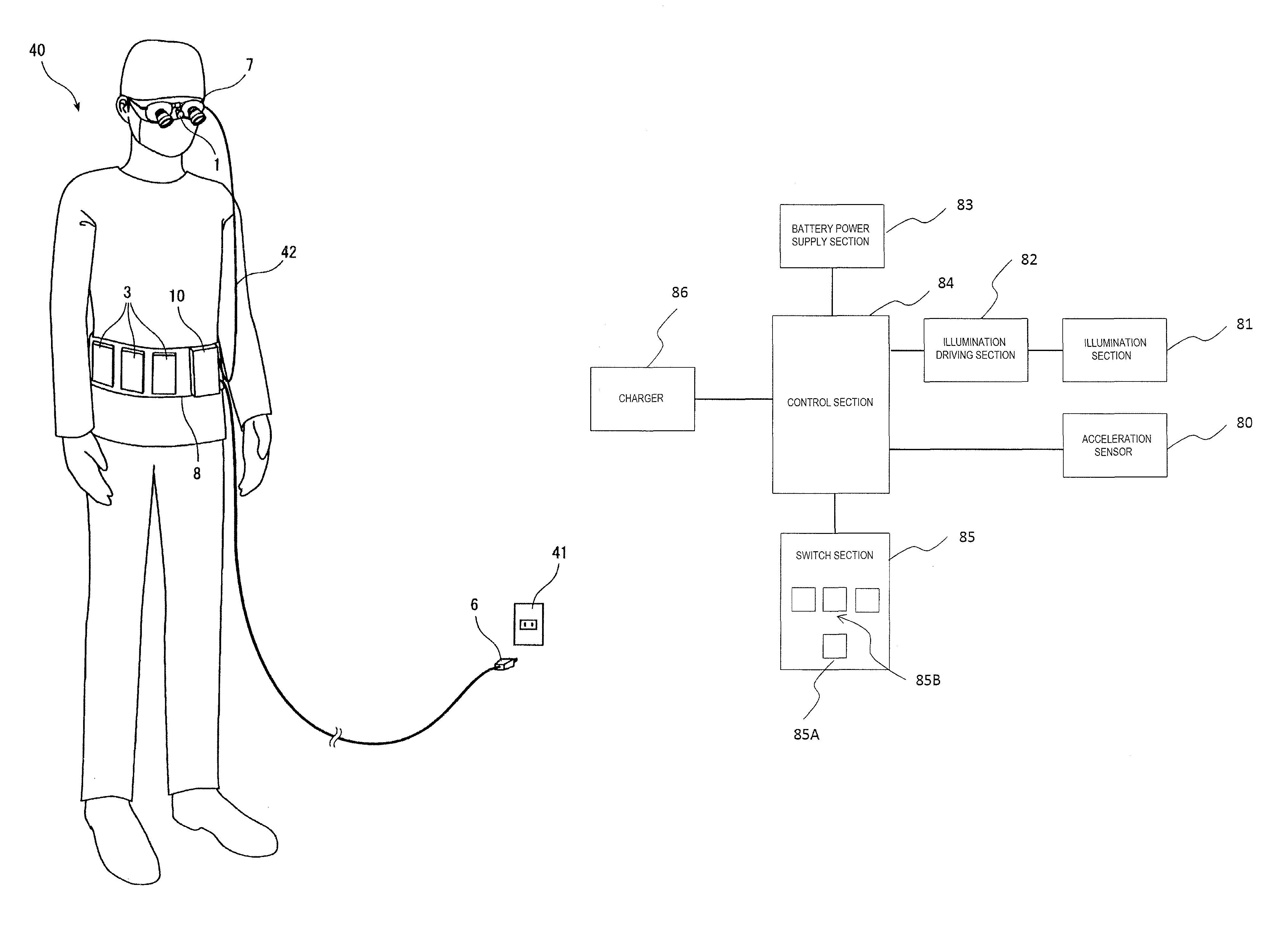
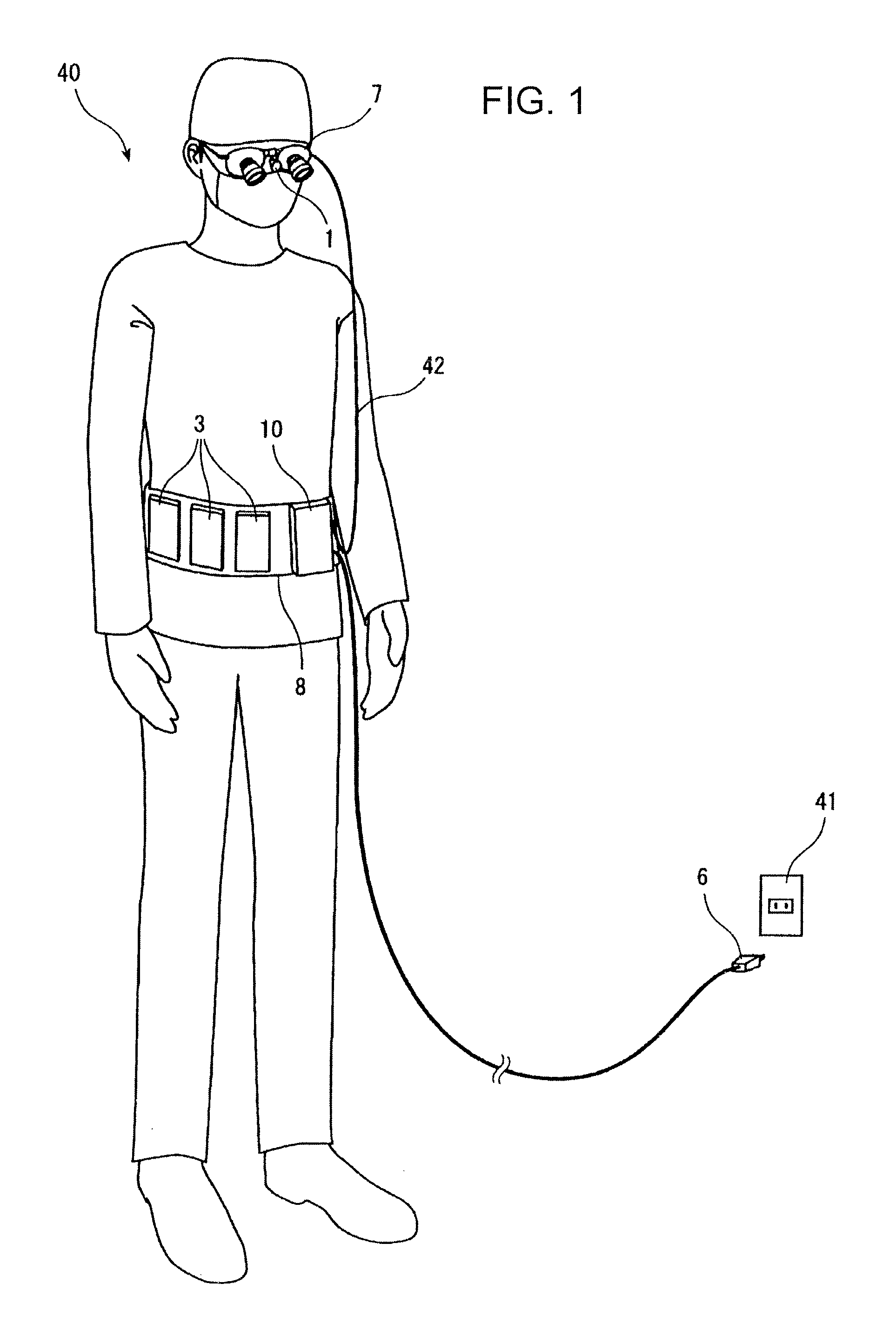
[0056]A medical light source device shown in FIG. 1 enables a power supply section to be held on the body of an operator. In FIG. 1, an illumination section 1 is held by a binocular loupe worn by an operator 40 and is worn on the head of the operator 40. Accordingly, in this Example, the binocular loupe functions as a holder 7. As a light source of the illumination section 1, an LED is used in this Embodiment, but the invention is not limited thereto.

[0057]Then, as part of the body of the operator 40, in this Embodiment, a holding belt 8 of the power supply section is wound around the waist. To the holding belt 8 are attached power supply sections 3 and a control unit 10. The power supply sections 3 are connected to the control unit 10, and the control unit 10 supplies an adequate driving current to the illumination section 1 through a code 42 to control illumination operation.

[0058]The power supply section may be an AC power supply or DC power supply. When the power supply section...

embodiment 2

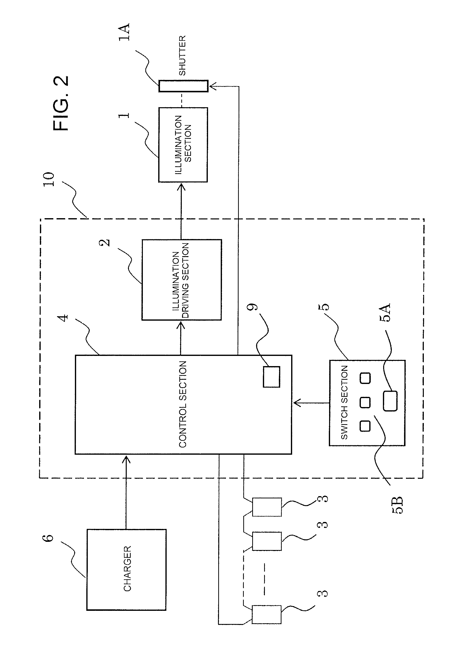
[0087]FIG. 8 is a block diagram illustrating a circuit configuration of the medical light source device , and is comprised of an illumination section 61 having an LED, a control section 54 provided with a microprocessor unit MPU and a current control circuit 62, a switch section 55, a battery power supply section 60 comprised of a plurality of connected rechargeable batteries, and an AC adapter as a charger 56 to charge the battery power supply section 60. Then, the microprocessor unit (hereinafter, simply referred to as MPU) of the control section 54 is programmed with processing procedures for controlling the peripheral devices.

[0088]The switch section 55 is comprised of a first switch 55A to light the illumination section 61, and second switches 55B, 55C to light the illumination section 61 with increase light quantities. When the second switches 55B, 55C are operated, the control section 54 controls the current control circuit 62 so as to change the average current value fed to ...

embodiment 3

[0142 of the invention will be described next. In this Embodiment, an acceleration sensor detects a motion of an operator, and the emission amount is controlled corresponding to the motion. In medical operations, it is assumed that the time with the need for applying a higher quantity of light to a part in the medical treatment such as, for example, cutting and suture of a blood vessel or minute portion and the like is almost 20% of the whole. Accordingly, by controlling to dim the illumination section 1 during a period except the time of almost 20%, it is possible to suppress power consumption of the battery power supply.

[0143]Accordingly, with the description given in FIG. 1, an acceleration sensor is provided together with the illumination section 1 in the holder 7 to detect a motion of the operator. Then, for a period during which the acceleration sensor detects acceleration, the period is judged as being an operation period without the need for applying a higher quantity of lig...


PUM


Abstract

It is an object to provide a medical light source device capable of securing a long illumination time required to use in operations in the medical field, and the medical light source device that is worn on the body of an operator to apply light to a target portion of the medical treatment is to cause an illumination section 81 to be worn on the body of the operator with a holder 7, and is provided with an acceleration sensor 80 that detects a motion of the operator, where a control section 84 controls a supply of current from a power supply section to the illumination section 81, while controlling to reduce illuminance of the illumination section 81 or to halt the passage of current to the illumination section 81 when the acceleration sensor 80 detects acceleration of a predetermined value or more.

Description

RELATED APPLICATIONS[0001]The present application is National Phase of International Application No. PCT / JP2011 / 078209 filed Dec. 6, 2011, and claims priority from Japanese Application No. 2011-004941, filed Jan. 13, 2011.TECHNICAL FIELD[0002]The present invention relates to a medical light source device for irradiating a treatment target portion with light by a light source in the medical treatment.BACKGROUND ART[0003]In medical light source devices used in the medical treatment (including surgical operations), a light source is placed in a rear upper position of an operator (practitioner) to irradiate the affected part. In the medical treatment, in increasing a quantity (illuminance) of light to irradiate the part targeted for the treatment, the light quantity of the entire light is increased, but in the case where the light is secured and installed in the ceiling or the like of the treatment room, there is a case that a sufficient quantity of light does not reach the part targete...

Claims


Application Information

Patent Timeline
Patent Type & Authority Patents(United States)
IPC IPC(8): H05B37/02G02B25/00G02B25/02G02B7/00H05B33/08F21V21/084A61B1/06F21V23/04G02C11/04F21W131/20F21Y101/02H05B44/00
CPCH05B37/0227A61B1/0692F21V21/084F21V23/0492G02B7/002G02B25/004G02B25/02G02C11/04H05B33/0815F21W2131/20F21Y2101/02Y02B20/44F21Y2115/10H05B45/37H05B47/115Y02B20/40
Inventor NAKAMURA, SHOICHI
Owner ACP JAPAN
Why Eureka
Try Eureka