Radiation image conversion panel

a technology of conversion panel and radiation image, which is applied in the direction of conversion screen, natural mineral layered products, instruments, etc., can solve the problems of reducing the durability of the conversion panel, reducing the adhesion strength, and reducing the sharpness, so as to achieve convenient handling, increase the adhesion strength, and suitability

Inactive Publication Date: 2005-05-12
KONICA MINOLTA MEDICAL & GRAPHICS INC
View PDF2 Cites 0 Cited by
  • Summary
  • Abstract
  • Description
  • Claims
  • Application Information

AI Technical Summary

Benefits of technology

[0059] It is preferable to provide the stimulating light absorbing layer so that the light transmittance of the protective layer at the wavelength of the stimulating light is from 98% to 50% of that of the same protective layer except that the stimulating layer absorbing layer is omitted. When the ratio is more than 98%, the effect of the invention is small and when the ratio is less than 50%, the illuminance of the radiation image conversion layer is considerably lowered.
[0060] The kind of the colorant to be employed is decided depending on the kind of the stimulable phosphor. As the stimulable phosphor for the radiation image conversion panel, one emitting light of from 300 to 500 nm by stimulation by stimulating light of from 400 to 900 nm is usually employed. Therefore, blue to green organic or inorganic colorants are usually employed.
[0061] Examples of the blue to green organic colorant include Sabon Fast Blue 3G manufactured by Hoechst Co., Ltd., Estrol Bril Blue N-3RL manufactured by Sumitomo Kagaku Co., Ltd., Sumiacryl Blue F-GSL manufactured by Sumitomo Kagaku Co., Ltd., D & C Blue No. 1 manufactured by National Aniline Co., Ltd., Spirit Blue manufactured by Hodogaya Kagaku Co., Ltd., Oil Blue No. 603 manufactured by Orient Co., Ltd., Quitone Blue A manufactured by Ciba-Geigy Co., Ltd., Aizen Carotin Blue GLH manufactured by Hodogaya Kagaku Co., Ltd., Lake Blue A, F and H manufactured by Kyouwa Sangyo Co., Ltd., Rhodarin Blue 6GH manufactured by Kyouwa Sangyo Co., Ltd., Primo Cyanine 6GX manufactured by Inahata Sangyo Co., Ltd., Bril Acid Green 6BH manufactured by Hodogaya Kagaku Co., Ltd., Cyanine Blue BNRS manufactured by Toyo Ink Co., Ltd., and Lyonol Blue SL manufactured by Toyo Ink Co., Ltd. Examples of blue to green inorganic colorant include Prussian blue, cobalt blue, cerulean blue, chromium oxide, and TiO2—ZnO—CoO—NiO type pigments.
[0062] As the support to be employed in the radiation image conversion panel according to the invention, ones capable of being made as a flexible sheet or a web are suitable for easiness of handling. From such the viewpoint, a plastic film such as cellulose acetate film, polyester film, poly(ethylene terephthalate) film, poly(ethylene naphthalate) film, polyamide film, polyimide film, triacetate film and polycarbonate film is preferred.
[0063] Though the thickness of the support may be varied depending on the kind of the material of the support, the thickness is usually from 80 μm to 1,000 μm and preferably from 80 μm to 500 μm.
[0064] The surface of the support may be either smooth or matted for raising the adhesiveness with the stimulable phosphor layer.

Problems solved by technology

It has been known that the unevenness of image density is degraded when heat is applied.
However, the durability of the conversion panel tends to be lowered because the scratches and the cracks on the protective layer surface tend to be formed in the course of the repeatedly use when the thickness of the protective layer is thin.
However, the thickness of the protective layer should be increased in the usual technology to obtain the durability for prolonged period in the apparatus so that degradation of the sharpness is resulted.
Problems that unevenness of the density other than the density variation caused by the subject occurs when-a film of polypropylene, poly(ethylene terephthalate) or poly(ethylene naphthalate) is used as protective layer, or the density unevenness caused by the coating of the resin composition containing fluorinated resin occurs.
However, a drawback is caused that the increasing of the haze ratio results further lowering of the sharpness.
However, the improvement of the sharpness is insufficient and the compatibility of high sharpness and low density unevenness cannot be satisfied yet.

Method used


Image

  • Radiation image conversion panel
  • Radiation image conversion panel
  • Radiation image conversion panel

Examples


example 1

>

(Preparation of Coated Type Stimulable Phosphor Layer)

[0114] To methyl ethyl ketone, 200 g of stimulable phosphor (BaFBr0.85I0.15:Eu2+0.001), 8.0 g of polyurethane resin (Pandex T5265 manufactured by Dainihon Ink Kagaku Kogyo Co., Ltd.) and 2.0 g of epoxy resin (EP1001 manufactured by Yuka Shell Epoxy Co., Ltd.) as a yellowing preventing agent were added and dispersed by a propeller mixer to prepare a coating liquid for forming a phosphor layer having a viscosity of 30 Pa.s at 25° C. The coating liquid was coated on poly(ethylene terephthalate) film having a thickness of 300 μm and dried. Thus a stimulable phosphor sheet which had a stimulable phosphor layer having a thickness of 230 μm was obtained.

(Preparation of Gas Accumulated Type Stimulable Phosphor Layer)

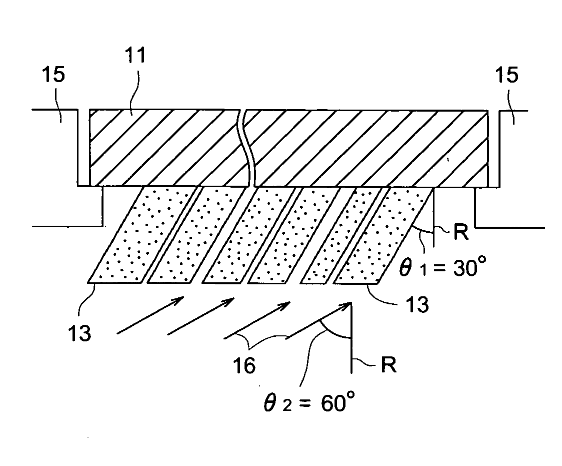
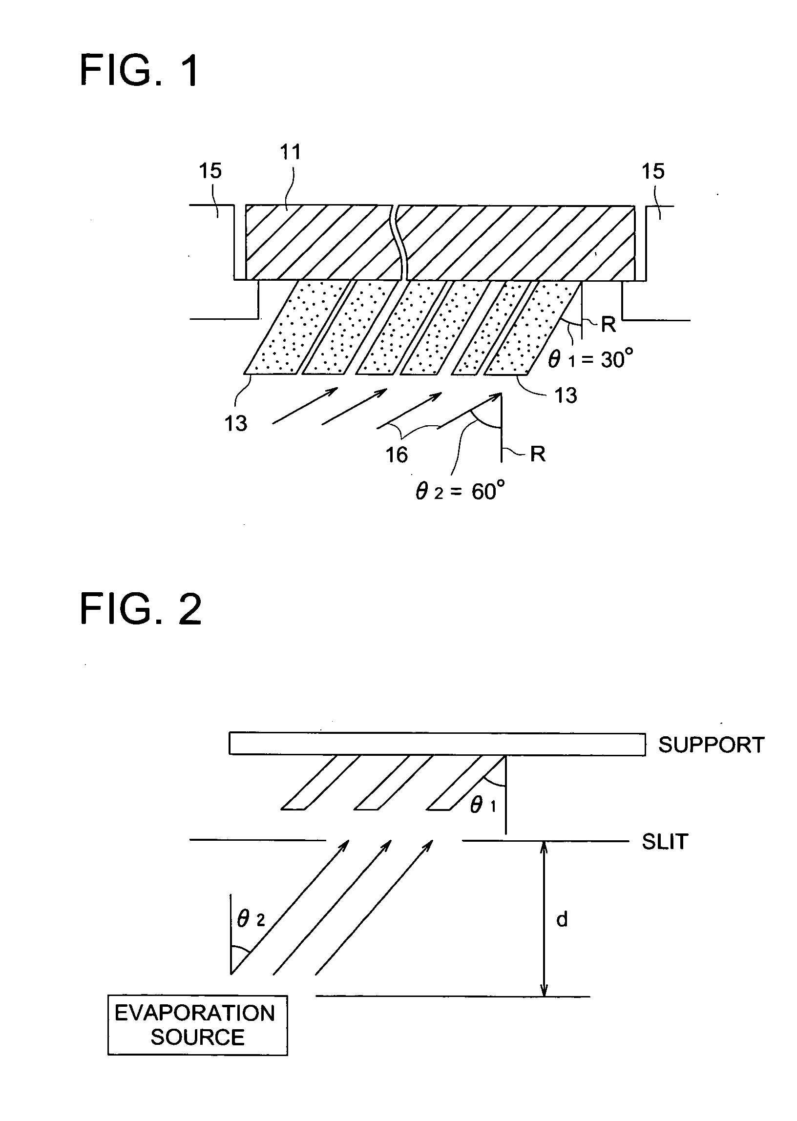
[0115] On the surface of a crystalline glass palate, manufactured by Nihon Denki Glass Co., Ltd., having a size of 410 mm×410 mm and a thickness of 1 mm, a stimulable phosphor layer comprising a stimulable phosphor of C...


PUM

PropertyMeasurementUnit
surface roughness Raaaaaaaaaaa
light transmittanceaaaaaaaaaa
thicknessaaaaaaaaaa

Abstract

A radiation image conversion panel comprising a phosphor sheet having a stimulable phosphor layer and a protective layer provided so as to cover the surface of the phosphor layer, wherein mean slope Δa of an outer surface of the protective layer not adjacent with the phosphor layer is from 0.01 to 0.1 and the surface roughness Ra in μm of the inner side or the phosphor sheet side of the protective layer is 0.05 μm to 0.45 μm, and the stimulable phosphor layer is provided by a coating method.

Description

[0001] This application is a continuation-in-part application of U.S. patent application Ser. No. 10 / 942,654, filed on Sep. 16, 2004.FIELD OF THE INVENTION [0002] The present invention relates to a radiation image conversion panel employing a stimulable phosphor, and relates in detail to a radiation image conversion panel having a high resistivity against heat, by which an image with high sharpness and without unevenness of image density can be obtained. BACKGROUND OF THE INVENTION [0003] Radiographic images such typically as X-ray images are widely employed in various fields, for example, in the medical diagnosis. To obtain the X-ray image, radiophotographic method is principally utilized in which radiation penetrated through a subject is irradiated to a phosphor layer, also called as a phosphor screen, and light emitted from the phosphor layer is irradiated to silver halide photographic light-sensitive material and then the light-sensitive material is developed to obtain a visible...

Claims


Application Information

Patent Timeline
Patent Type & Authority Applications(United States)
IPC IPC(8): C09K11/00G21K4/00C09K11/02C09K11/08C09K11/77G01T1/00G03B42/02G03B42/08
CPCG21K4/00C09K11/7733
Inventor KUDO, SHINJISHOJI, TAKEHIKOMORIKAWA, OSAMU
Owner KONICA MINOLTA MEDICAL & GRAPHICS INC
Why Eureka
Try Eureka