Imaging system

a technology of imaging system and camera, applied in the field of imaging system, can solve the problems of easy damage to the lens when dropping the imaging system, increase in costs, and easy shake of the camera, and achieve the effect of improving the balance of the center of gravity

Active Publication Date: 2013-09-19
RICOH KK
View PDF8 Cites 65 Cited by
  • Summary
  • Abstract
  • Description
  • Claims
  • Application Information

AI Technical Summary

Benefits of technology

[0010]The present invention has been made in view of the above circumstances, and an object of the present invention is to p

Problems solved by technology

In an imaging system in which a lens surface projects from a housing, a lens is easily damaged when dropping the imaging system.
Such a technique described in Patent Document 1 requires the push button for opening and closing a lens cover, resulting in an increase in costs.
When the arrangemen

Method used


Image

  • Imaging system
  • Imaging system
  • Imaging system

Examples


embodiment 1

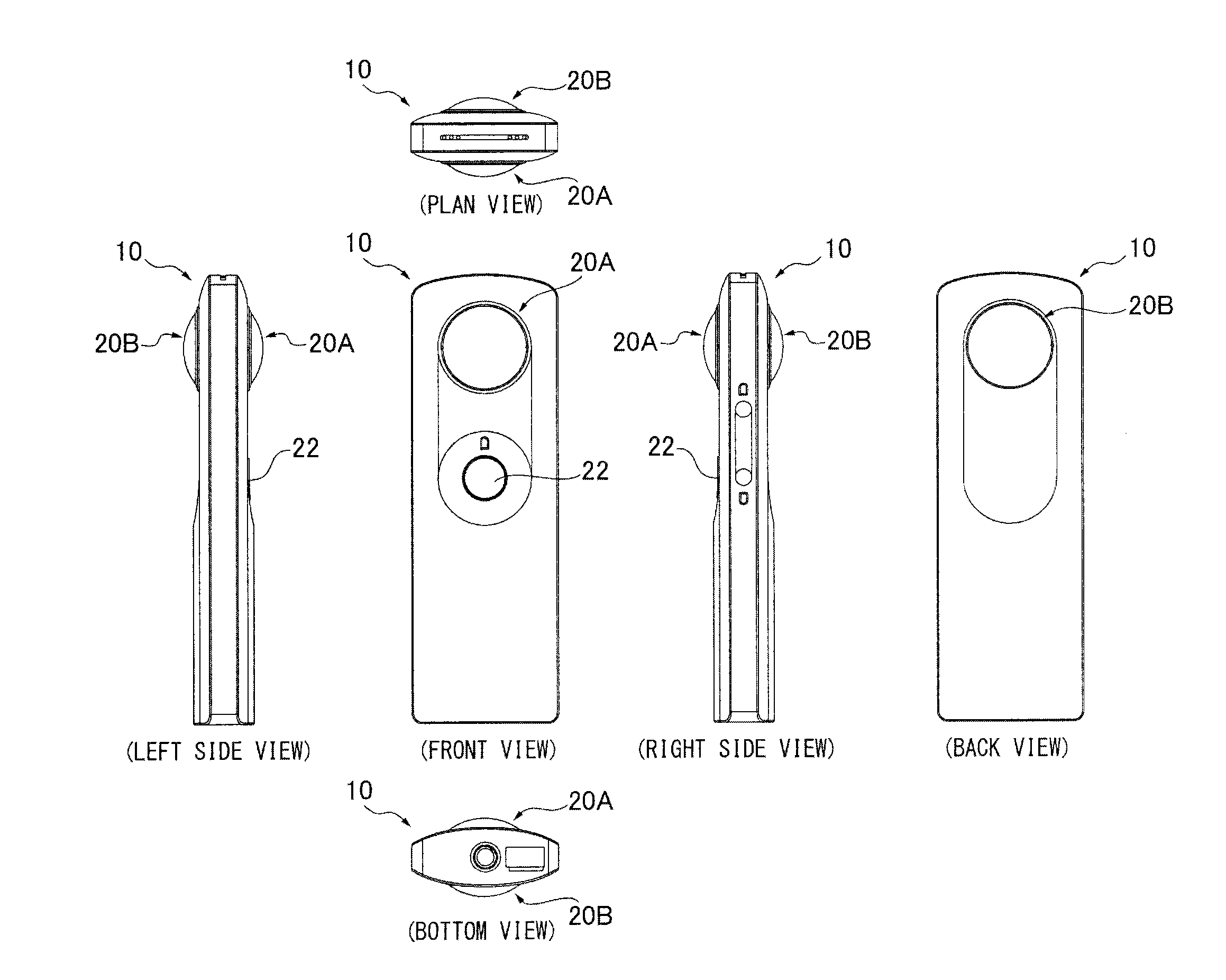
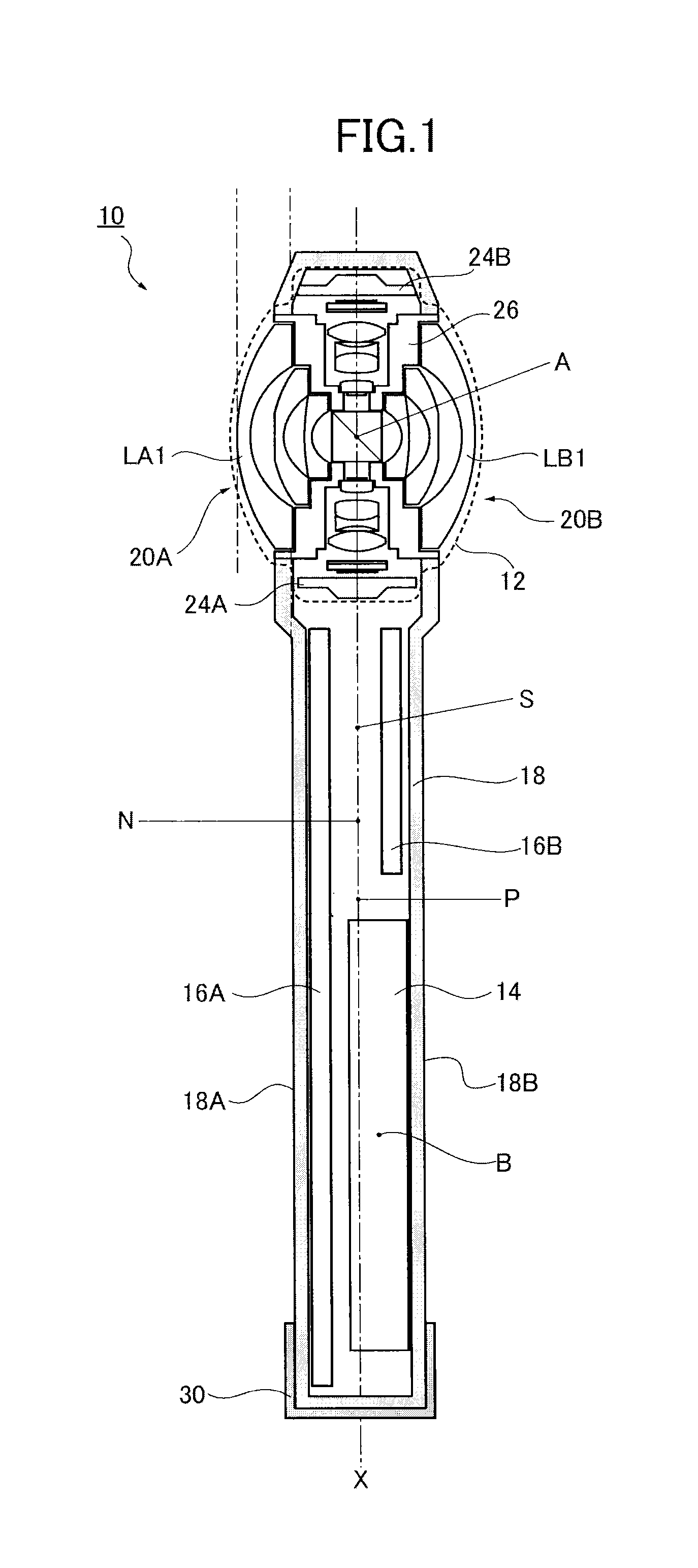
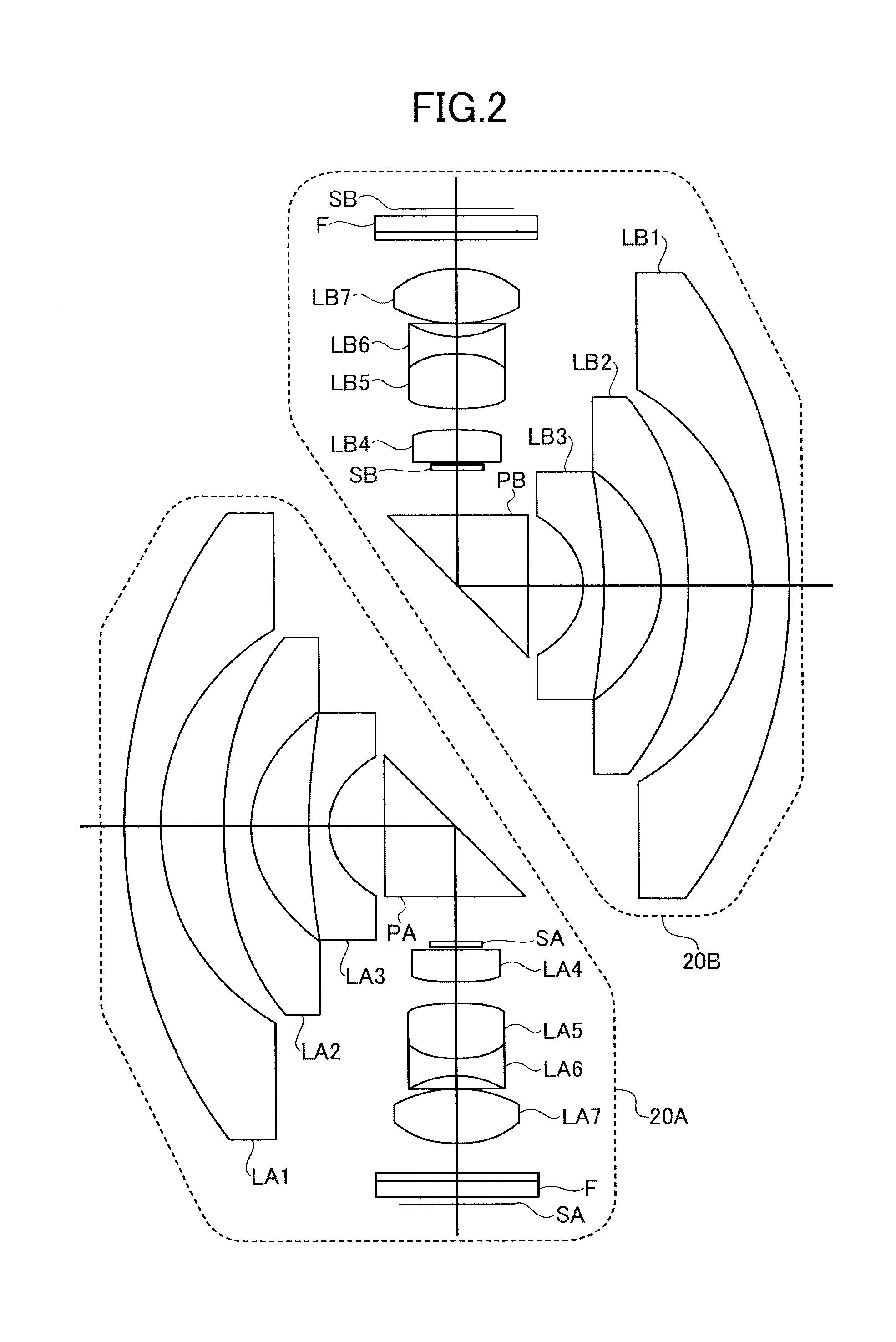
[0073]The omnidirectional imaging system 10 having a linear shape illustrated in FIG. 1 was obtained. Each of the image-forming optical systems 20A, 20B had seven lenses in six groups. In this configuration, the second lens LA2, LB2 from the object side and the seventh lens LA7, LB7 from the object side were a plastic lens. The plastic lens was formed by using a plastic resin material (specific weight 1.1) of E48R of Zeonex (registered trademark). The lens barrel 26 was formed by using a polycarbonate (PC+GF) material with glass having a specific weight of 1.3.

[0074]The curvature radius r and the effective diameter R of the first lens LA1, LB1 were 17 mm and 20 mm, respectively, and the sag amount h of the first lens LA1, LB I was about 3.25 mm. The projection amount of the first lens LA1, LB1 from the housing surface 18A, 18A was about 5 mm. The above condition 4 therefore was satisfied.

[0075]Measuring the gravity center A of the imaging body 12 in which the lenses LA1-7, LB1-7, ri...

embodiment 2

[0077]The omnidirectional imaging system 50 having a spherical shape illustrated in FIG. 4 was obtained. Each of the image-forming optical systems had seven lenses in six groups. In this configuration, the second lens LA2, LB2 from the object side and the seventh lens LA7, LB7 from the object side were a plastic lens of E48R of Zeonex (registered trademark). The lens barrel 26 was formed by using a polycarbonate (PC+GF) material with glass.

[0078]The curvature radius r and the effective curvature radius R of the first lens LA1, LB1 were 17 mm and 20 mm, respectively, and the sag amount h of the first lens LA1, LB1 was about 3.5 mm. The above condition 4 therefore was satisfied.

[0079]Measuring the gravity center A of the imaging body 52 in which the lenses LA1-7, LB1-7, right-angle prisms PA, PB, lens barrel and imaging elements were combined, the gravity center P of the entire imaging system 50 and the gravity center B of the battery 54, the distance AP was 15 mm, and the distance BP...

embodiment 3

[0080]The omnidirectional imaging system 10 having a linear shape illustrated in FIGS. 5, 6 was obtained by using the lens barrel 26 and the image-forming optical systems 20A, 20B similar to Embodiment 1. The curvature radius r and the effective diameter R of the first lens LA1, LB1 were 17 mm and 20 mm, respectively, and the sag amount h of the first lens LA1, LB1 was about 3.25 mm. The projection amount of the first lens LA1, LB1 from the housing surface 18A, 18A was about 5 mm. The above condition 4 therefore was satisfied.

[0081]Measuring the gravity center A of the imaging body 12 in which the lenses LA1-7, LB1-7, right angle prisms PA, PB, lens barrel 26 and imaging elements 24A, 24B were combined, the gravity center P of the entire imaging system 10 and the gravity center B of the battery 14, the distance AP was 47 mm, and the distance BP was 32 mm. The weight m of the imaging body 12 was 17 g and the weight M of the battery 14 was 25 g. Moreover, measuring the distance AN bet...


PUM


Abstract

An imaging system includes an imaging body having an optical system and an imaging element, a power supplier configured to supply power to the imaging element, and a housing configured to hold the imaging body and the power supplier, wherein the optical system includes at least one optical element projecting from the housing, and a distance AP between a gravity center A of a portion including the optical system and a gravity center P of the entire imaging system and a distance BP between a gravity center B of the power supplier and the gravity center P of the entire imaging system satisfy the following condition.
AP>BP

Description

PRIORITY CLAIM[0001]The present application is based on and claims priority from Japanese Patent Application No. 2012-060242, filed on Mar. 16, 2012, and Japanese Patent Application No. 2012-277671, filed on Dec. 20, 2012, the disclosures of which are hereby incorporated by reference in their entirety.BACKGROUND[0002]1. Field of the Invention[0003]The present invention relates to an imaging system in which a lens surface projects from a housing.[0004]2. Description of the Related Art[0005]An imaging system using a plurality of wide-angle lenses such as a fisheye lens or a super-wide-angle lens is known as an imaging system which images all directions at one time In such an imaging system, an image from each lens is projected on the same or corresponding sensor, and the projected images are combined by an image process, so as to produce an omnidirectional image.[0006]When an imaging system is created with a small number of optical components, an angle of view assigned to each lens te...

Claims


Application Information

Patent Timeline
IPC IPC(8): H04N5/225
CPCH04N5/2254H04N5/2251H04N23/50H04N23/51H04N23/65H04N23/698G02B5/04G02B13/06
Inventor MASUDA, KENSUKETERAO, NORIYUKIIRINO, YOSHIAKITANAKA, TOMONORIIMAE, NOZOMIHARADA, TORUTAKENAKA, HIROKAZUYAMAMOTO, HIDEAKISAWAGUCHI, SATOSHIBESSHO, DAISUKESATOH, HIROYUKISHOHARA, MAKOTO
Owner RICOH KK
Why Eureka
Try Eureka