Firearm sights and assemblies

a technology for sights and firearms, applied in the field of optics firearm sights, can solve the problems of obstructing the slide of the firearm, obstructing the reflex optics, and affecting the shooting effort of shooters,

Active Publication Date: 2022-08-04
SPRINGFIELD
View PDF22 Cites 0 Cited by
  • Summary
  • Abstract
  • Description
  • Claims
  • Application Information

AI Technical Summary

Benefits of technology

[0019]The rearward end and / or rearward-facing side of the housing preferably includes serrations. The serrations preferably reduce glare that may be directed toward an eye of a shooter of the firearm (e.g., anti-glare serrations). The serrations may comprise a series of elongate peaks separated by elongate valleys. The peaks may be truncated. Truncated peaks may define flat surfaces extending parallel to the rearward end and / or rearward-facing side of the housing.
[0020]Serrated surfaces of the housing are preferably not coplanar with one another. More preferably, serrated surfaces of the housing are oblique to one another. Additionally or alternatively, serrated surfaces of the housing may be spaced from one another (e.g., spaced apart along the length of the housing). Advantageously, such arrangements can aid in dispersing light that reflects from the housing so as to reduce the total illuminance that may reach a shooter's eye in the event of a glare.
[0035]Firearm assemblies comprising the sights disclosed herein preferably have a laterally extending protrusion of the sight housing with a greater width than a corresponding width of a serration on a slide of the firearm assembly. Preferably, the laterally extending protrusion of the sight has a greater height than a corresponding height of the serration. Preferably, the laterally extending protrusion has a greater width and / or height than all of the serrations on the slide of the firearm. Preferably, the laterally extending protrusion extends laterally outward beyond the outermost surface of the serration. Advantageously, such arrangements can make it easier for an operator to grasp and, therefore, manually operate the slide of the firearm.

Problems solved by technology

Reflex optics, however, often obstruct part of the slide of the firearm.
Additionally, as reflex optics typically extend upwards from the top of the firearm, they can frustrate efforts by a shooter to grasp the slide of the firearm from above—as some shooters may need to do to remove and / or load a cartridge in the firearm during operation.

Method used


Image

  • Firearm sights and assemblies
  • Firearm sights and assemblies
  • Firearm sights and assemblies

Examples


Embodiment Construction

[0055]For the purpose of promoting an understanding of the principles of the invention, reference will now be made to the embodiments illustrated in the drawings and specific language will be used to describe the same. It will nevertheless be understood that no limitation of the scope of the invention is thereby intended. Any alterations and further modifications in the described embodiments, and any further applications of the principles of the invention as described herein are contemplated as would normally occur to one skilled in the art to which the invention relates. One embodiment of the invention is shown in great detail, although it will be apparent to those skilled in the relevant art that some features that are not relevant to the present invention may not be shown for the sake of clarity.

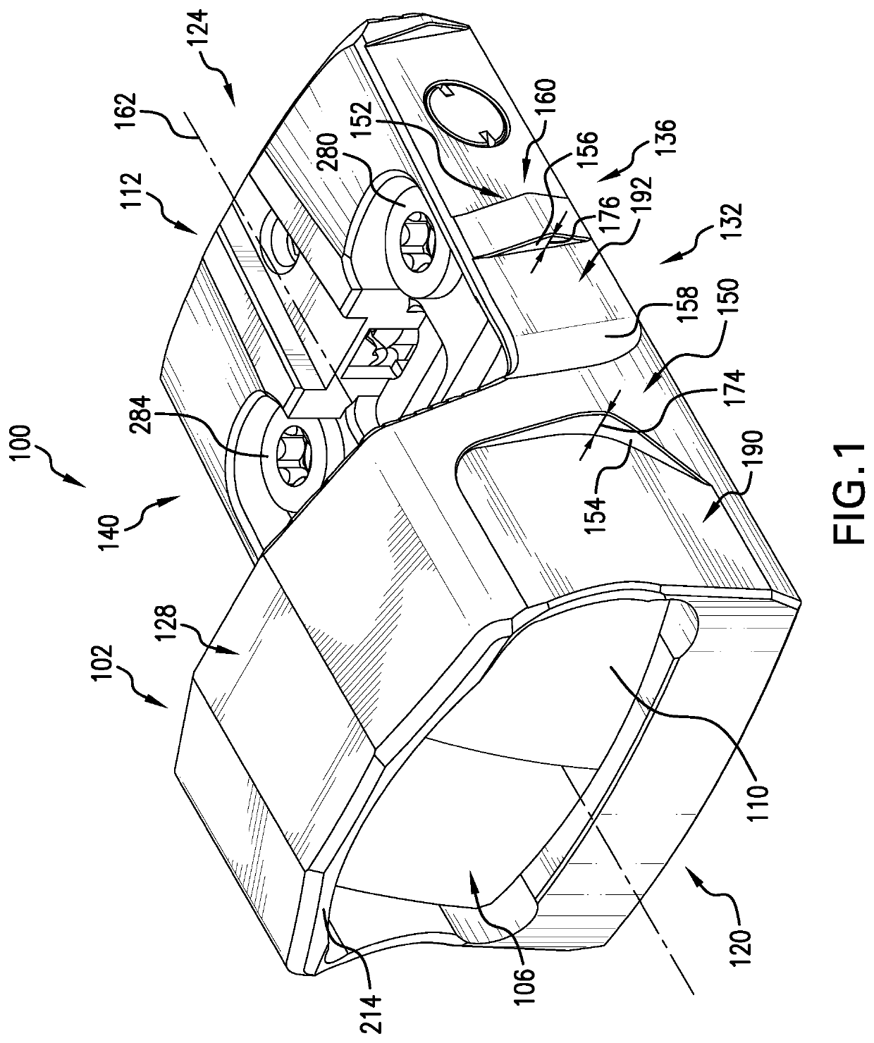
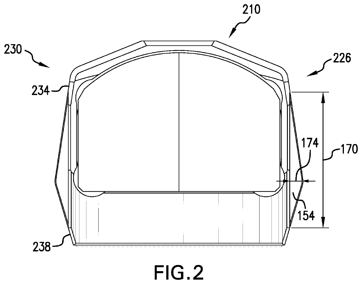
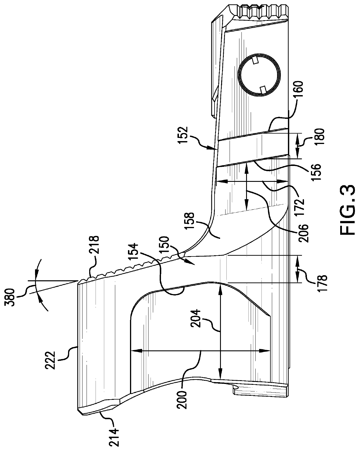
[0056]The present disclosure pertains generally to sights for firearms. More specifically, the present disclosure pertains to optical firearm sights having a lens and / or an iron sight con...


PUM


Abstract

Sights of the present disclosure comprise a housing supporting an optical sighting element, such as one or more lenses or iron sights. A first lateral side of the housing has a laterally-extending protrusion and a lead-in portion forward of the laterally-extending portion. In some arrangements the lead-in portion is laterally-inward of an outermost surface of the laterally-extending protrusion and has a surface roughness of less than 50 μm. In some instances, the laterally-extending protrusion has a width of at least 1 mm and the lead-in portion has a length of at least five times the width of the laterally-extending protrusion.

Description

BACKGROUND OF THE INVENTION[0001]The present disclosure pertains generally to sights for firearms and assemblies of both. More specifically, the present disclosure pertains to optical firearm sights, such as reflex optics.[0002]Reflex optics are a type of firearm sight that is often mounted to the slide of a firearm (e.g., a pistol). A reflex optic has a light emitter (e.g., an LED or laser) and a reflective transparent element (e.g., a lens such as a glass plate which may have a coating). The light emitter directs light towards the reflective transparent element which, in turn, reflects the light towards the direction of the shooter. When shooting the firearm, the shooter looks through the reflective transparent element and uses the reflected light to aim the firearm.[0003]Reflex optics are popular as they can be configured to reduce the effects of parallax and can also allow for a shooter to see more of the target as compared to other sighting devices, such as iron sights. Reflex ...

Claims


Application Information

Patent Timeline
Patent Type & Authority Applications(United States)
IPC IPC(8): F41G1/30G02B23/16
CPCF41G1/30G02B23/16
Inventor REESE, DENNIS J.MCKELVAIN, STEPHEN H.BALLARD, NICKLEACH, PETER J.
Owner SPRINGFIELD
Why Eureka
Try Eureka