Lighting apparatus

a technology of light shielding and light source, which is applied in the direction of lighting and heating apparatus, fixed installation, and support devices for lighting and heating, can solve problems such as prone to glare, and achieve the effect of reducing glare and improving light shielding properties

Inactive Publication Date: 2010-02-18
TOSHIBA LIGHTING & TECH CORP +1
View PDF35 Cites 61 Cited by
  • Summary
  • Abstract
  • Description
  • Claims
  • Application Information

AI Technical Summary

Benefits of technology

[0007]The present invention provides a lighting apparatus having improved light shielding properties that lead to a reduction in glare.
[0010]The light-emitting devices are located on a plurality of concentric circles with different radii. Since the light-emitting devices are arranged concentrically, the shielding angles can easily be set for the reflective surfaces corresponding to the individual light-emitting devices.
[0015]In the lighting apparatus in an aspect of the invention, the reflective surfaces and blind member are formed in the manner described above, so that the glare of the outermost light-emitting device located across the center of the light-emitting devices is intercepted by the reflective surface corresponding to the outermost light-emitting device the moment the glare of the inside light-emitting devices are intercepted by the blind member. Thus, the lighting apparatus can reduce the glare.
[0019]Thus, according to the present invention, there is provided a lighting apparatus having improved light shielding properties that lead to a reduction in glare.

Problems solved by technology

However, each LED is liable to cause glare, since it is a point light source, as well as being highly directional and able to emit highly luminous light.

Method used


Image

  • Lighting apparatus
  • Lighting apparatus
  • Lighting apparatus

Examples


first embodiment

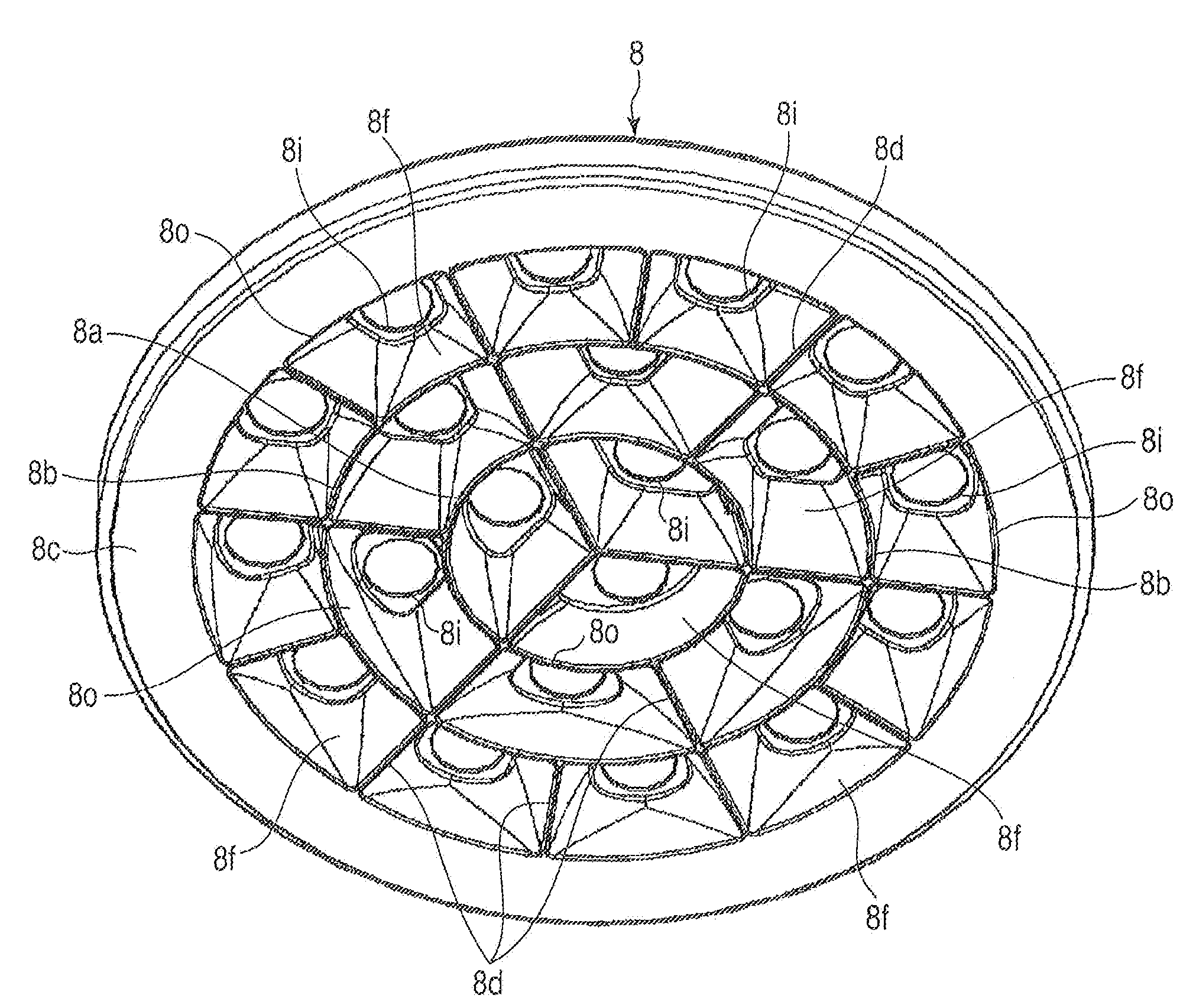
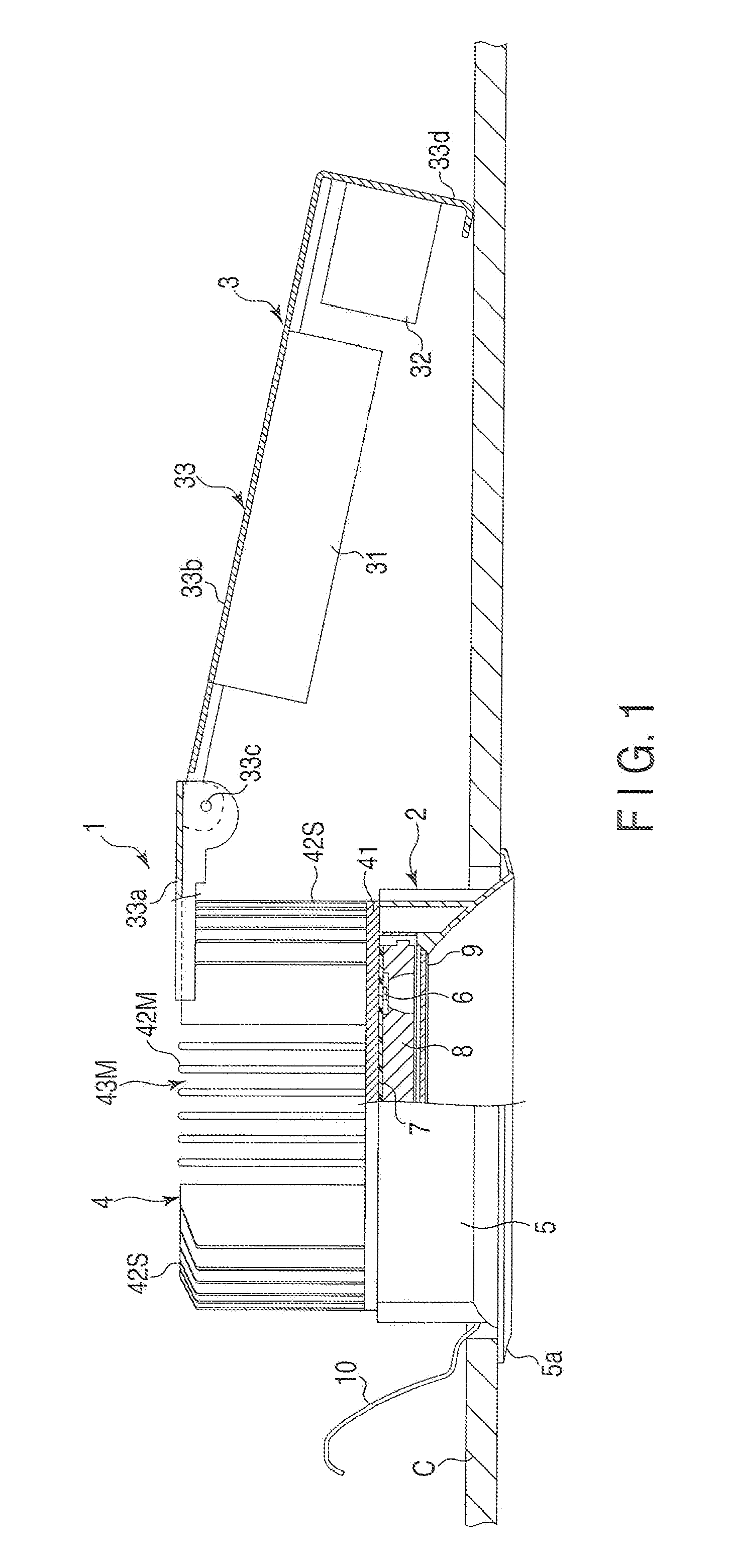
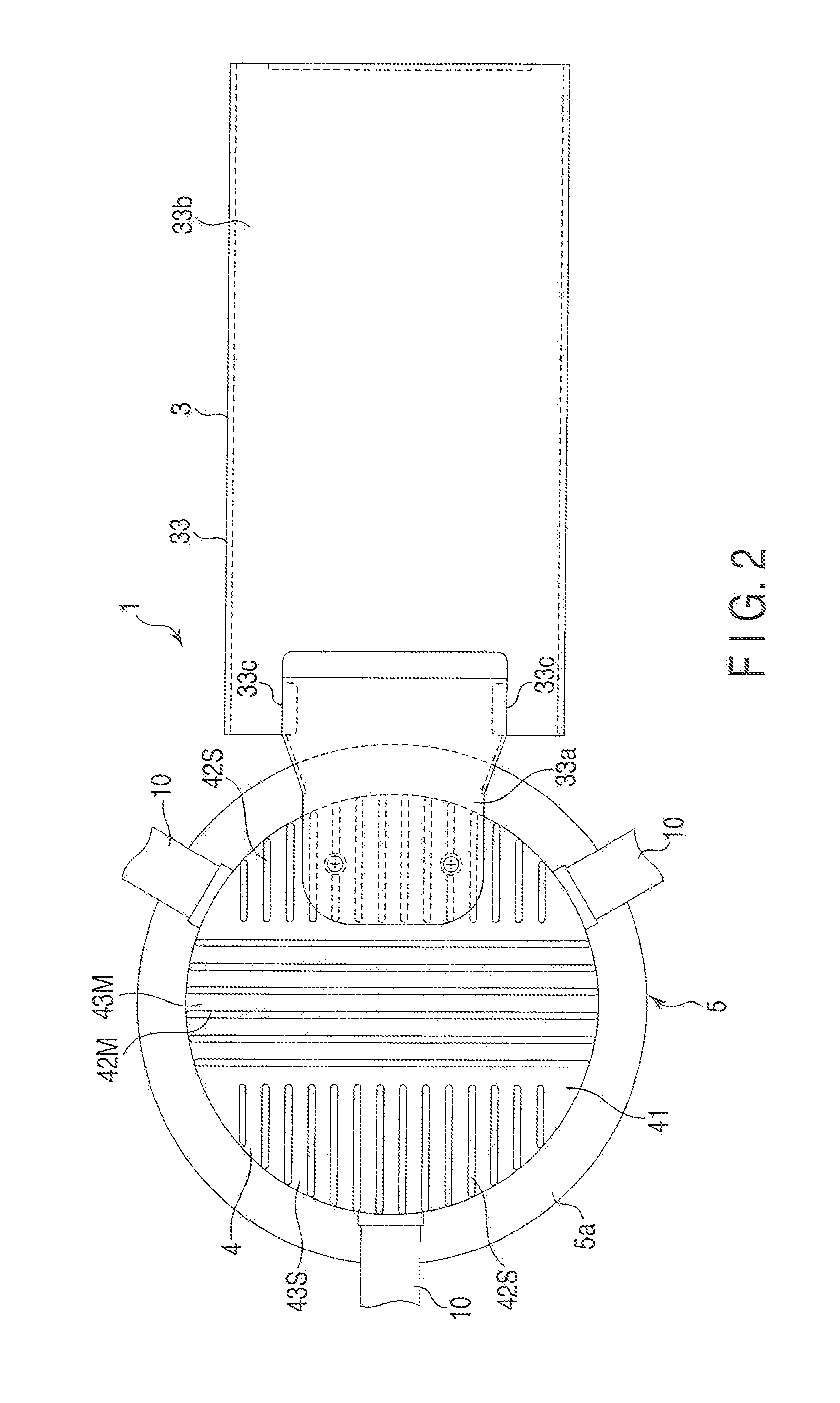
[0039]A lighting apparatus 1 according to the present invention will now be described with reference to FIGS. 1 to 7D. FIGS. 1 to 3 show a down-light of a type embedded in a ceiling C, as an example of the lighting apparatus 1. The lighting apparatus 1 is provided with a light source unit 2 and power source unit 3 connected to each other. The light source unit 2 includes a thermal radiator 4, blind member 5, LEDs 6, substrate 7, reflector 8, and translucent cover 9. In the description herein, the side on which lights are emitted is sometimes referred to as “front” or “obverse”; the opposite side, as “back” or “reverse”; and a direction across the direction of light emission, as “lateral” or “transverse”.

[0040]As shown in FIGS. 1 and 2, the radiator 4 is a so-called heat sink for use as thermal radiation means of the lighting apparatus 1. The radiator 4 is formed of a highly thermally conductive material, such as a die casting of aluminum alloy. The outer surface of the radiator 4 is...

fifth embodiment

[0075]A lighting apparatus 1 according to the invention will now be described with reference to FIG. 14. This lighting apparatus 1 is contained in a housing H mounted above the ceiling C. The housing H is provided with a hull H1 enclosing the lighting apparatus 1 and a pair of brackets H2 mounted on the hull H1. Each bracket H2 is fixed to a beam on the ceiling C.

[0076]Further, the blind member 5 of the lighting apparatus 1. is composed of first and second blind members 51 and 52. The first blind member 51 is fixed together with a thermal radiator 4 to stems H3 that extend from the inner surface of the hull H1. The second blind member 52 is formed with a conical surface spreading toward the projection side. The second blind member 52 is inserted from the projection side into the first blind member 51 through a panel of the ceiling C. The second blind member 52 may be either secured to the ceiling C or coupled to the first blind member 51.

fourth embodiment

[0077]In this lighting apparatus 1, like that of the fourth embodiment, the overall length and shielding angle of the blind member 5 can easily be changed by replacing the second blind member 52 with another one with a different length, internal space, and angle. Thus, according to this lighting apparatus 1, the blind member 5 can be modified according to the installation environment, and glare can be reduced.

[0078]In each of the embodiments described herein, the LEDs 6, substrate 7, reflector 8, and translucent cover 9 may be unitized as a single light-emitting assembly. This light-emitting assembly includes a terminal and connector on the reverse side of the substrate 7 opposite from the projection side. The terminal is connected to the power circuit 31, while the connector is fitted to the base 41 of the radiator 4. A mounting portion of a main body of the apparatus is provided with sockets corresponding to the terminal and connector. The light emitter can be removed from the mai...


PUM


Abstract

A lighting apparatus is provided with a plurality of light-emitting devices, a substrate, a blind member, and a reflector. The reflector is formed with a plurality of reflective surfaces corresponding to the light-emitting devices, individually. The shielding angle at which light emitted from that one of the light-emitting devices which is located on the outermost periphery is intercepted by the reflective surface corresponding to the outermost light-emitting device is greater than shielding angles at which light emitted from the light-emitting devices located inside the outermost light-emitting device is intercepted by the reflective surfaces corresponding to the inside light-emitting devices.

Description

CROSS-REFERENCE TO RELATED APPLICATIONS[0001]This application is based upon and claims the benefit of priority from prior Japanese Patent Application No. 2008-272281, filed Oct. 22, 2008, the entire contents of which are incorporated herein by reference.BACKGROUND OF THE INVENTION[0002]1. Field of the Invention[0003]The present invention relates to a lighting apparatus using light-emitting devices, such as LEDs, as its light sources and having improved light shielding properties.[0004]2. Description of the Related Art[0005]Lighting apparatuses have been developed that use light-emitting devices, such as LEDs, as their light sources. A lighting apparatus provided with light-emitting diodes (LEDs) and reflector is described in Jpn. Pat. Appln. KOKAI Publication No. 2008-186776. The LEDs for use as light sources are arranged concentrically at regular intervals on a substrate. The reflector has reflective surfaces corresponding to the LEDs, individually.[0006]A lighting apparatus with L...

Claims


Application Information

Patent Timeline
Patent Type & Authority Applications(United States)
IPC IPC(8): H01L33/00
CPCF21S8/02F21S8/026F21V7/0083F21V21/04F21V29/77F21Y2101/02F21V29/507F21V29/75F21V29/76F21V23/026F21Y2115/10
Inventor HIGUCHI, KAZUNARIMORIYAMA, TAKAYOSHIHASHIMOTO, SUMIOKUMASHIRO, SHINICHIHONDA, YUTAKANEZU, KENJI
Owner TOSHIBA LIGHTING & TECH CORP
Why Eureka
Try Eureka