Anti-glare device for projector

a projector and anti-glare technology, applied in static indicating devices, instruments, television systems, etc., can solve problems such as false detection, reduced person, and reduced light intensity of vertical images, and achieve the effect of reducing glar

Inactive Publication Date: 2005-09-20
MAXELL HLDG LTD
View PDF10 Cites 66 Cited by
  • Summary
  • Abstract
  • Description
  • Claims
  • Application Information

AI Technical Summary

Benefits of technology

[0006]In view of the above problems, it is an object of the present invention to provide an image display apparatus that can reduce glare by reducing projected light entering into eyes while keeping a picture projected on a screen during a presentation using the projected image by a speaker on the platform even when (1) someone enters into the projection path accidentally, (2) the speaker standing in the projection path turns his / her face to the projector, or (3) a picture is displayed in an enlarged manner or trapezoidal distortion is compensated because of setting of the projector and the screen.

Problems solved by technology

However, in the conventional displaying method for alarming the risk, it may still be likely that any person enters into the projection path and such risk can be accommodated merely by calling for further attention.
On the other hand, in the patent document 1, there is a problem in that the light intensity of the image in the vertical direction including the person is reduced because the area of the person entering into the projection path is detected and, in the patent document 2, in turn, there is a problem in that, when the person area is extracted and then masked by using various sensors such as, in particular, a CCD sensor, person extraction accuracy may be degraded and, therefore, false detection may occur due to insufficient exposure of the CCD.

Method used


Image

  • Anti-glare device for projector
  • Anti-glare device for projector
  • Anti-glare device for projector

Examples


first embodiment

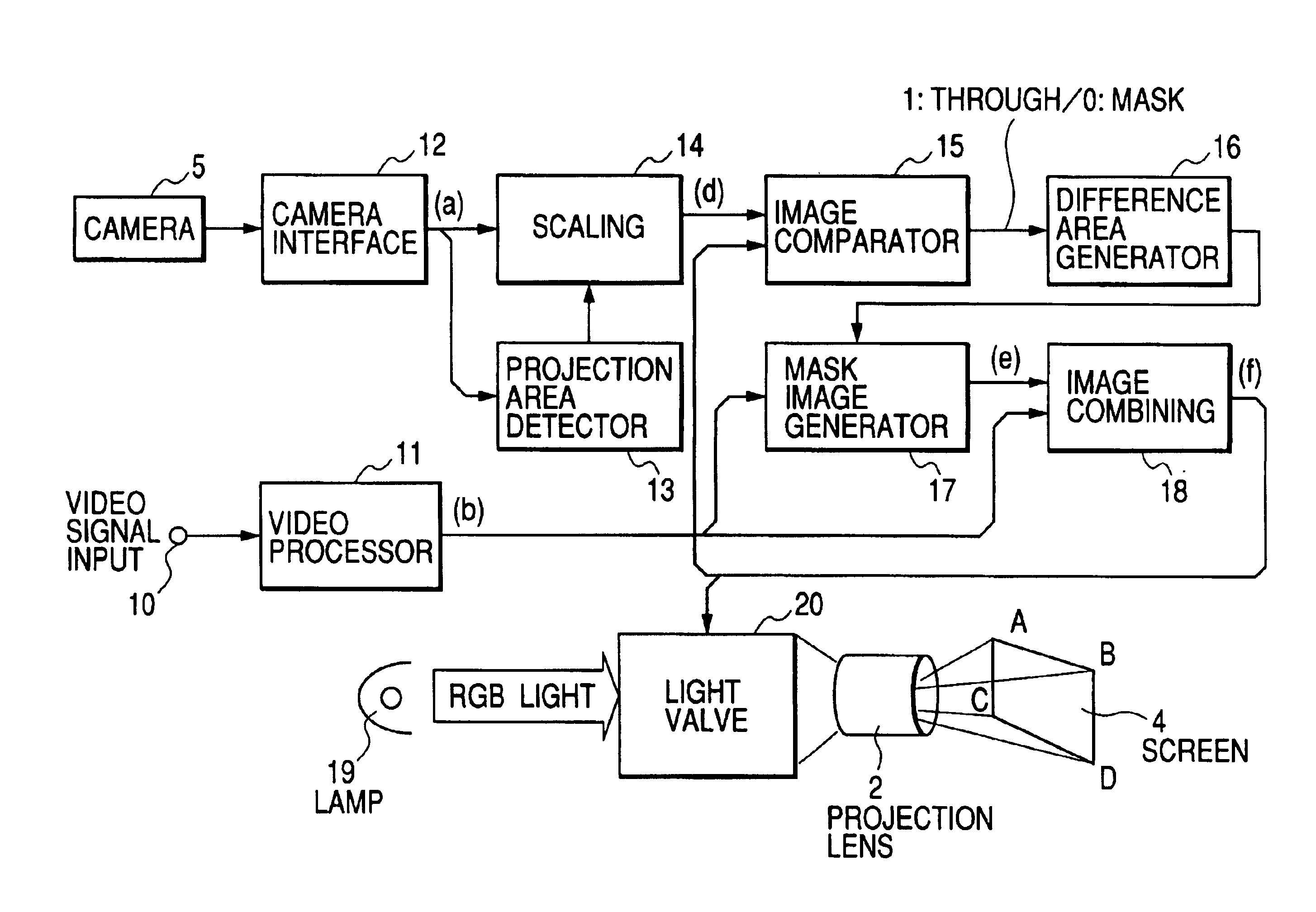
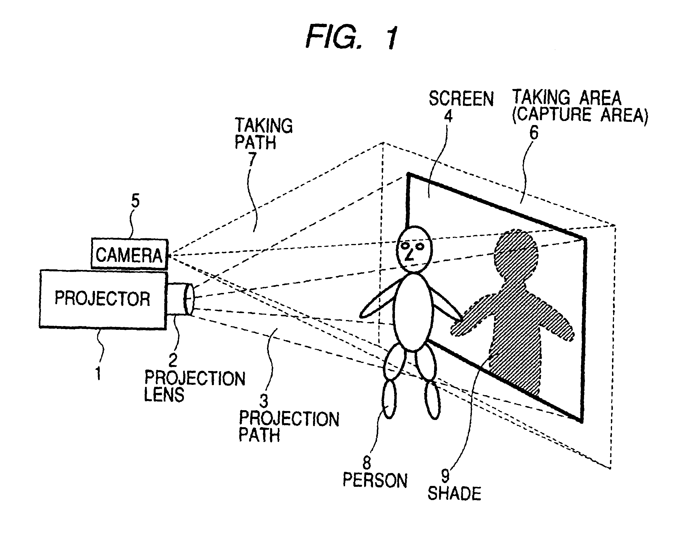
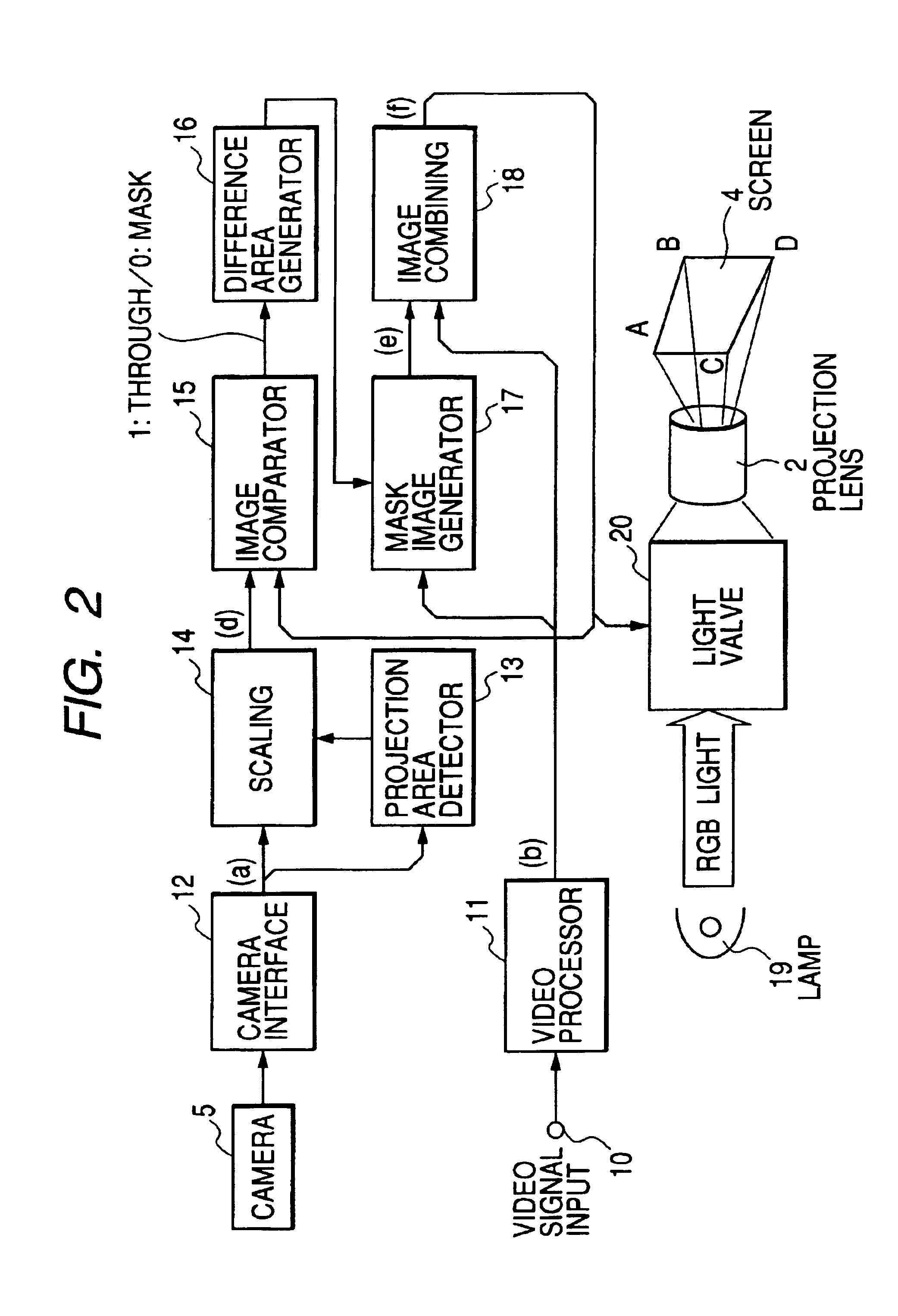
[0016]FIG. 1 is a schematic diagram showing an exemplary system configuration in which a front projection type projector apparatus according to the present invention, a screen and a speaker on the platform are disposed. Further, FIG. 2 is a block diagram showing an image processing unit according to the present invention. Still further, FIGS. 6A-6G are schematic diagrams showing image information in each processing block.

[0017]Here, an embodiment using a light valve type display device that controls an amount of light transmitted by a liquid crystal or reflected by a reflecting mirror according to a gray-scale level of each pixel in image information will be described. The display device is not limited to a particular type and it may be any display device such as a three-pipe type or a CRT type. Further, though the case in which one image display device as shown in FIG. 2 is included is described, the present invention may also be applied to the case in which the image display devic...

second embodiment

[0049] described above, even when the person is moving, the accuracy of the masked area can be ensured periodically while the person in the projection path may not suffer the glare.

[0050]Further, though the case in which the image signal combining unit 18 selects the displayed image during the frame period when the capture is permitted (when the displayed image is not changed) or the image on which the masked image is superimposed during the frame period when the capture is prohibited (when the displayed image is masked) as the image to be projected has been described in the second embodiment, an image in which the intensity level of an area corresponding to the person area is reduced may be selected during the frame period when the capture is permitted. In this case, in a manner similar to the first embodiment, the image comparator 15 is configured to compare the displayed area extraction image from the scaling unit 14 with the image having the reduced intensity level from the imag...

third embodiment

[0054] described above, it is possible to extract the person with high accuracy and without dependence on the displayed image information and, further, cost reduction can be implemented easily because the infrared light can be obtained by splitting it from the white light source.

[0055]Next, a fourth embodiment of the present invention will be described with reference to FIG. 5. Here, elements having reference numerals identical to those described in the first and third embodiments have substantially similar features, description of which will be, therefore, omitted.

[0056]In FIG. 5, there is shown a thermo-camera 24. Here, the light source is similar to the one in FIG. 2.

[0057]According to this configuration, the thermo-camera 24 senses the distribution of the temperature emitted from the person standing in the projection path and the distribution of the temperature emitted from the screen 4 and conveys the information to the camera interface 12. The person area detector 22 extracts ...


PUM

PropertyMeasurementUnit
frame frequency Fvaaaaaaaaaa
areaaaaaaaaaaa
image sizeaaaaaaaaaa

Abstract

There is provided a safe image display apparatus for projecting an image on a screen that can minimize a stimulus to eyes, retinae and optic nerves from projected light entering into the eyes directly. By comparing a displayed image captured by a camera with an input image signal, a changed area is detected as a difference area and, then, a projected image signal is generated wherein a picture area image signal in the input image signal that corresponds to this difference area is masked by a black signal. The obtained projected image signal is projected onto the screen.

Description

BACKGROUND OF THE INVENTION[0001]The present invention relates to a safety improvement technique in a projector type image display apparatus that is configured to display visual information by projecting it on a screen.[0002]In a conventional liquid crystal projector that is configured to project an image on a screen in front of the projector, as there is a risk in that eyes of a speaker or other persons on the platform are stimulated by strong light when the persons enter into the path of the light projected from the projector to the screen and look toward the projector, such risk must be prevented by indicating precautions on the main body of the projector and so on.[0003]Further, as described in Japanese Patent Laid-open No. 2000-305481 and Japanese Patent No. 2994469, there has been proposed a method for preventing such risk by providing detection means for detecting whether there is an object in a projection path and control means for controlling an amount of light from a proje...

Claims


Application Information

Patent Timeline
Patent Type & Authority Patents(United States)
IPC IPC(8): H04N5/74G03B21/00G03B21/14G02F1/13
CPCG03B21/26H04N5/74H04N9/3194Y10S362/80
Inventor KOBORI, TOMOKIHARUNA, FUMIONOZAWA, TSUNEYUKI
Owner MAXELL HLDG LTD
Why Eureka
Try Eureka