
Illumination and imaging system with glare reduction and method therefor

a technology of glare reduction and imaging system, applied in the field of imaging system, can solve the problems of insufficient mitigation of disruptive glare, inhibiting the ability to recognize imaged features, and many conventional approaches that employ active light illumination, etc., and achieve the effect of reducing glare and reducing glare in the imag

Active Publication Date: 2008-04-10
APTIV TECH LTD
View PDF6 Cites 66 Cited by
  • Summary
  • Abstract
  • Description
  • Claims
  • Application Information

AI Technical Summary

Benefits of technology

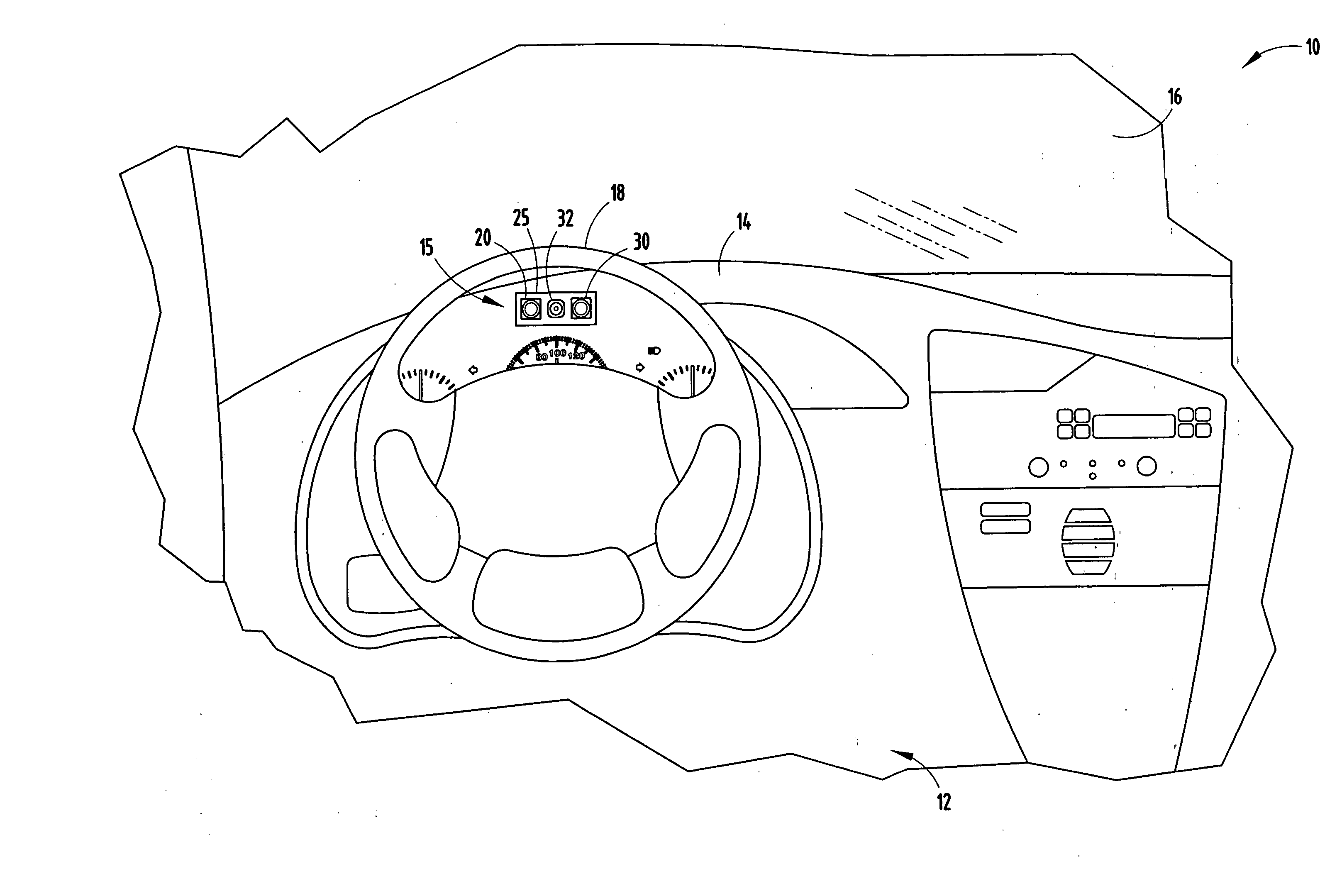
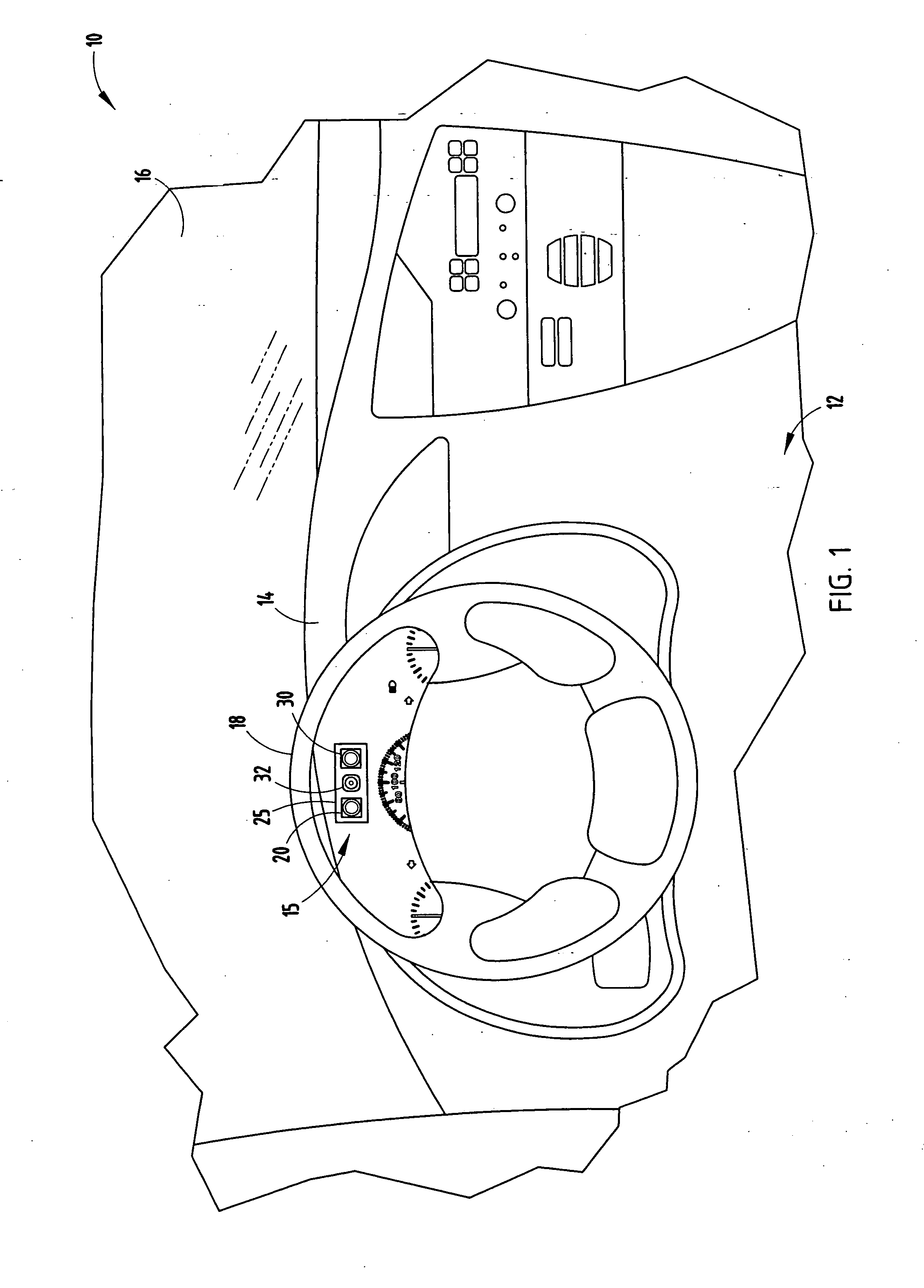
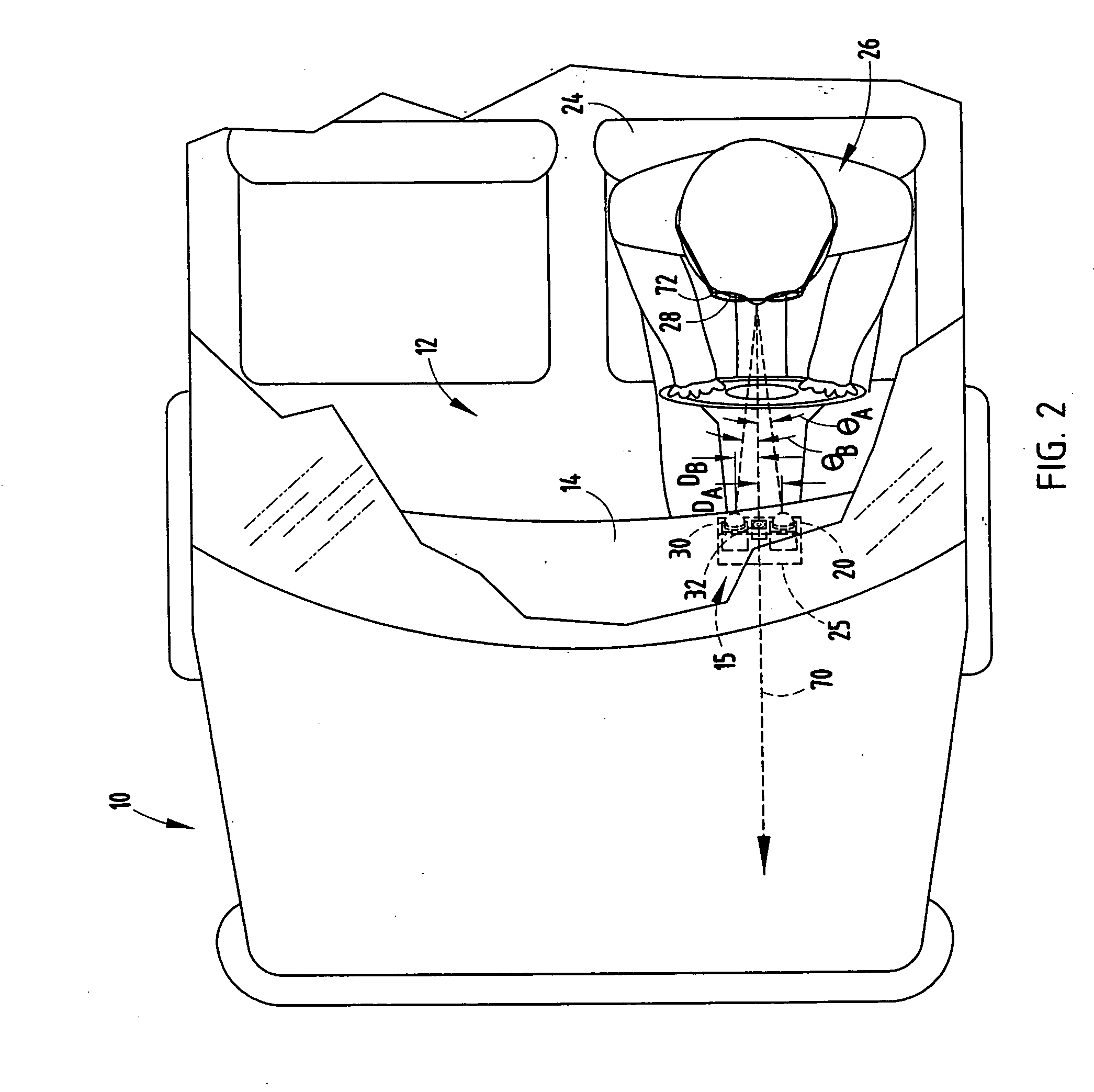
The present invention provides a system and method for reducing glare in images of an object, such as eyes, by illuminating them with alternating light beams and capturing multiple frames of the object in successive video frames. These frames are then combined using a pixel-wise min operation to create a single image with reduced glare. This technology is useful for improving the recognition of objects, such as drivers wearing corrective lenses, by reducing glare in the captured images.

Problems solved by technology

Many conventional approaches that employ active light illumination suffer from drawbacks.
The resultant glare may occur at the regions of interest near the eye(s) of the subject person, thus inhibiting the ability to recognize imaged features.
Thus, relocation of the illumination source, particularly in a vehicle, may not adequately mitigate the disruptive glare.
The glare problem is further aggravated in that nominal movements of the subject's head may shift the glare so that the glare again occludes the eye.
While the aforementioned system generally reduces glare in the captured images, the system employs illuminators positioned relatively far from the camera which complicates the packaging of the system in the vehicle cockpit and, thus, typically adds to cost and difficulty in installing such a system.
Additionally, the glare resulting from illumination by the illuminators may not always be sufficiently reduced.

Method used


Image

  • Illumination and imaging system with glare reduction and method therefor
  • Illumination and imaging system with glare reduction and method therefor
  • Illumination and imaging system with glare reduction and method therefor

Examples


first embodiment

[0038]Referring to FIG. 5, the method 100 for removing glare and controlling illumination is illustrated, according to a The method 100 described in FIG. 5 is employed with the use of a global shutter camera, according to one embodiment. Method 100 begins at step 102 and proceeds to set a counter equal to zero (0) in step 104. In decision step 106, method 100 determines if the counter is equal to a zero (0) or a one (1). If the counter is equal to zero, method 100 proceeds to energize the left LED in step 110, and reads the current video frame in step 112. The current video frame had been formed during the previous image formation period, i.e., while the right LED was energized. Next, method 100 stores the video frame to frame R in step 114, and then sets the counter equal to one (1) in step 116. Thereafter, method 100 proceeds to perform the pixel-wise min operation in step 130 to combine the multiple frames illuminated by left and right light beams to generate picture image I wit...

second embodiment

[0041]In addition to removing glare resulting from the reflection of light from either of the illuminators 20 and 30, the system 15 may further remove glare and shadows caused by external energy light sources according to a In doing so, the light illumination controller 34 controls activation of the first and second illuminators 20 and 30 so as to sequentially switch among the following three states: activating only the first illuminator 20, activating only the second illuminator 30, and deactivating both illuminators 20 and 30, and thereafter repeating the three state sequences. In doing so, video frames are captured which include the following frame sequence: L, R, N, L, R, N, etc., where L and R represent video frames when the left and right illuminators 20 and 30 are illuminated, respectively, and N represents video images when a video image is captured with no illumination from the light illuminators 20 and 30. Assuming the video imaging camera 32 is a linear regime of operati...


PUM


Abstract

A system and method are provided for actively illuminating and capturing images of an object, such as a driver of a vehicle to reduce glare. The system includes a video imaging camera orientated to generate images of the subject object (e.g., eye(s)) in successive video frames. The system also includes first and second light sources operable to illuminate the object one at a time. The system further includes a processor for processing the image by performing pixel-wise min operation to combine multiple frames into a single frame to reduce glare in the image. The system may remove glare caused by the illuminators and caused by external energy sources.

Description

TECHNICAL FIELD[0001]The present invention generally relates to imaging systems and, more particularly, relates to a system and method for illuminating, capturing, and processing video images of an object, such as a person's eye(s), in a manner that reduces glare such as that caused by light reflections.BACKGROUND OF THE INVENTION[0002]A variety of video imaging systems have been proposed for use on-board vehicles to monitor the driver and / or passenger(s) in the vehicle. Some proposed video imaging systems include one or more cameras focused on the driver of the vehicle to capture images of the driver's face. The captured video images are processed to determine various facial characteristics of the driver including position, orientation, and movement of the driver's eyes, face, and head. Given the determined driver facial characteristics, such as the driver's eye positioning and gaze, vehicle control systems can provide enhanced vehicle functions.[0003]One proposed vehicle control s...

Claims


Application Information

Patent Timeline
Patent Type & Authority Applications(United States)
IPC IPC(8): H04N5/222G06V10/141
CPCA61B3/113G06T5/50G06K9/2027A61B5/18A61B5/163G06V10/141
Inventor KISACANIN, BRANISLAVNEWMAN, TIMOTHY J.
Owner APTIV TECH LTD
Learn More