
Adaptive external vehicle illumination system

a technology for external vehicles and illumination systems, applied in lighting and heating apparatus, transportation and packaging, lighting support devices, etc., can solve problems such as back-dazzle and traffic blinding effects, and achieve the effects of reducing glare, enhancing light efficacy, and enhancing the quality of all-over illumination

Active Publication Date: 2013-10-03
IP CONSULTING
View PDF4 Cites 59 Cited by
  • Summary
  • Abstract
  • Description
  • Claims
  • Application Information

AI Technical Summary

Benefits of technology

The patent describes a new vehicle headlamp system that uses a microprocessor to automatically adjust the brightness and direction of the light beams based on external light conditions, including the direction of traffic and the need for visibility. This system provides improved driving comfort and safety, meeting standard regulations for motor vehicle lighting. The headlamp can also be controlled using voice commands, and can adjust its output to reduce blinding effects and improve visibility without the need for manual switching. Overall, this technology provides a more efficient and effective way to control vehicle lights in response to external conditions.

Problems solved by technology

The fundamental ideas behind this application had risen out of the necessity to find a design solution for the complex subject of vehicular lighting devices which until present remain manually controlled with relatively poor performance results in respect to the forward direction and around curve visibility, back-dazzle and incoming traffic blinding effects.

Method used


Image

  • Adaptive external vehicle illumination system
  • Adaptive external vehicle illumination system
  • Adaptive external vehicle illumination system

Examples


Embodiment Construction

[0017]Constructive and Functional Objectives Pursued and Implemented by this Application

[0018]The main constructive and functional objectives of this application for which the claims are made, are enumerated below:[0019]a) To create a single physical asymmetric-geometry body containing the automatic light emitting system LEDs / Laser, built as a headlamp assembly which is applicable to any type of vehicle (terrestrial, nautical or airborne) and providing for all the front illumination, direction signaling lights, distress signaling and also providing rear-end signaling and reverse driving light controls,[0020]b) To automatically control the headlamp light intensity and direction in order to create an adaptive illumination system which responds to the environment illumination conditions, to produce a constant and uniform selective omnidirectional illumination over the whole scene ahead without high contrast zones or penumbra for increased visibility, reduced fatigue and to facilitate a...


PUM


Abstract

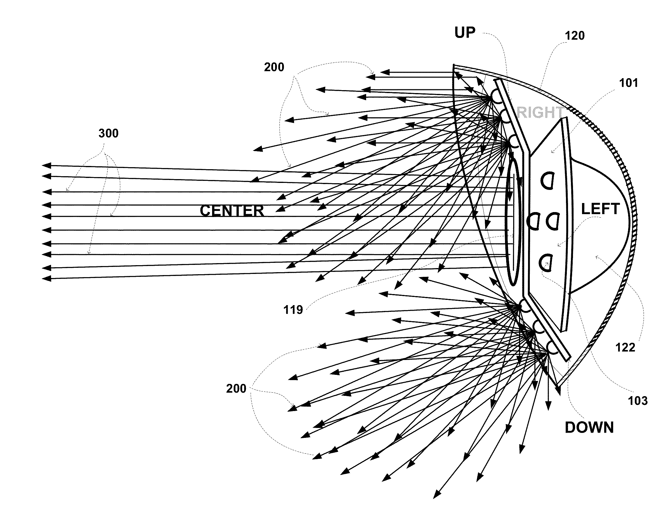
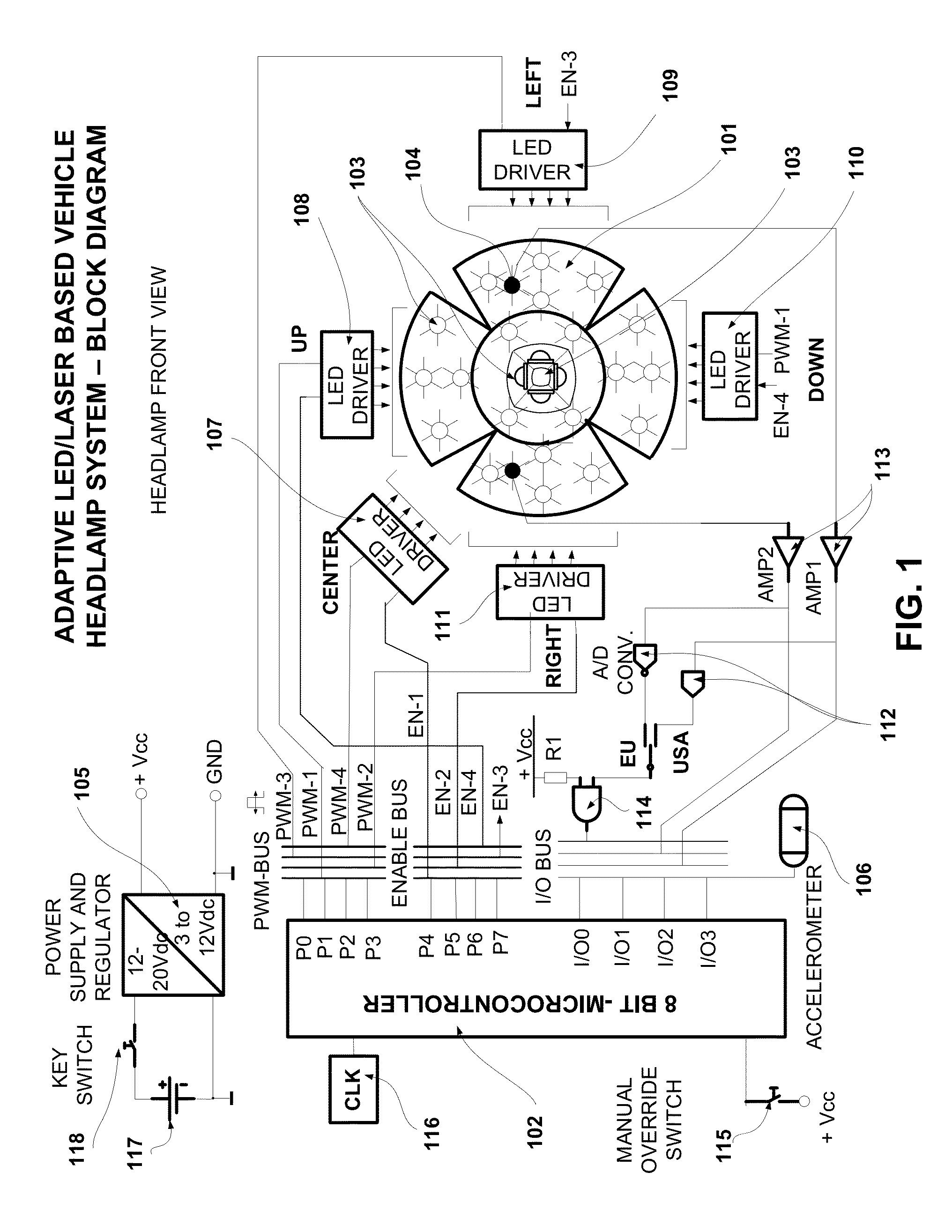
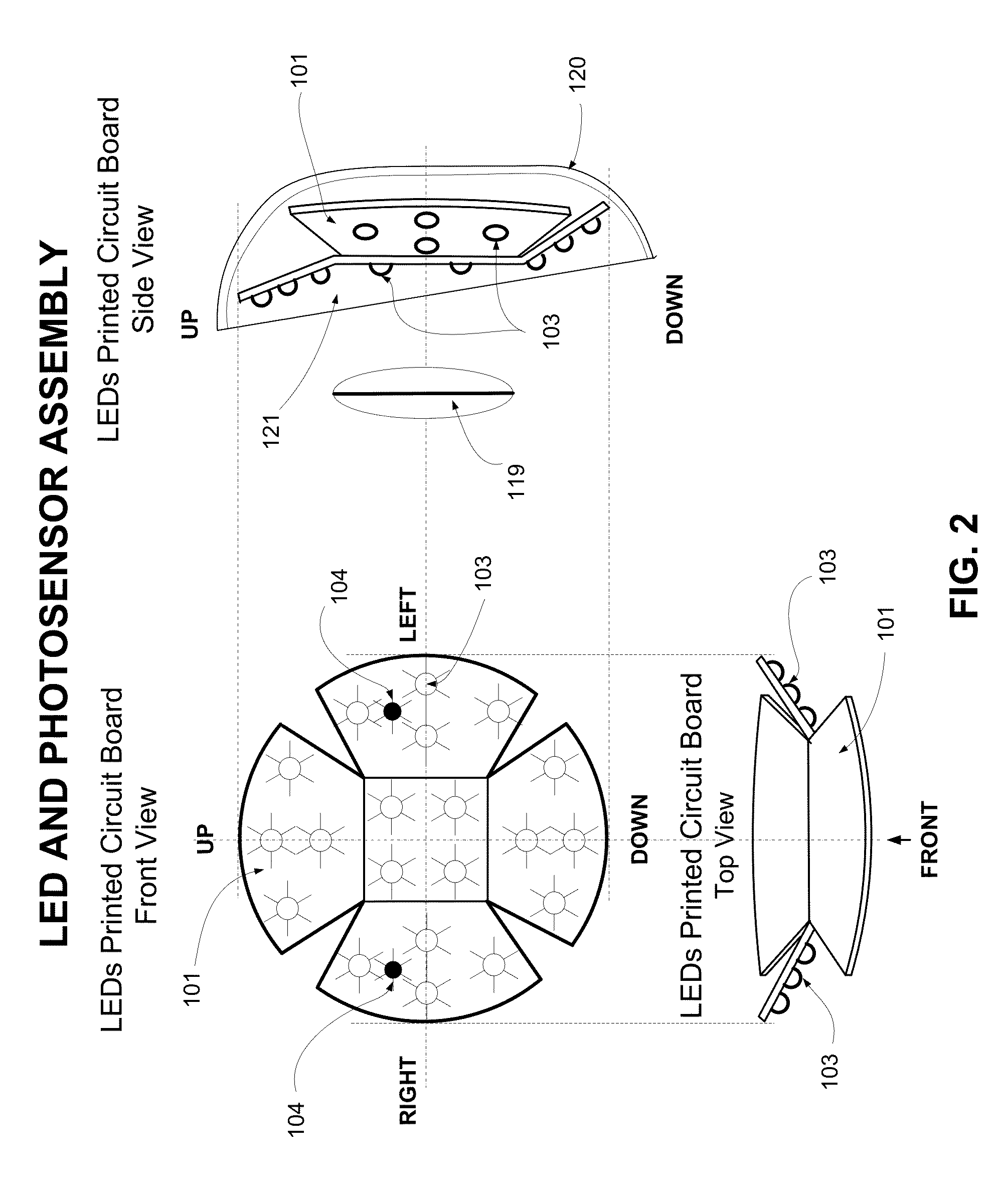
An asymmetric geometry headlamp for vehicular use is built as a multifaceted three dimensional body which has multiple light emitting devices (LEDs and / or laser emitters) installed on its angled facets, hence forming a multipurpose illumination apparatus within a single assembly which is designed to provide; a low beam with a wide illuminated area covering 2PiSteradians, a high beam all position and signaling lights. A microprocessor based system runs real time, continuously adaptive control routines for day and night conditions and provides the electric signals necessary for the independent control of the luminous intensity, direction and color spectrum to each facet of the headlamp's LEDs (light emitting diodes) and for the high beam. Multiple photo-sensors, CCD or CMOS video cameras, position encoders and accelerometers provide the feedback signals used in the automation of all lighting functions in a system designed to completely replace the manual actuation of lights on vehicles.

Description

SUMMARY OF INVENTION[0001]The fundamental ideas behind this application had risen out of the necessity to find a design solution for the complex subject of vehicular lighting devices which until present remain manually controlled with relatively poor performance results in respect to the forward direction and around curve visibility, back-dazzle and incoming traffic blinding effects. This application comprises of a microprocessor controlled headlight system providing adaptive output response of all illumination parameters as they are defined by luminous intensity, distribution of the luminous flux to needed to create the optimum road illumination patterns, by the direction of illumination as well as the necessity to change the emitters' radiated spectrum for improved visibility and for signaling purpose. The control system is designed to automatically respond to the external light conditions and relies on electronic feedback signals received from photo-sensors or video input, angula...

Claims


Application Information

Patent Timeline
Patent Type & Authority Applications(United States)
IPC IPC(8): B60Q1/04F21V7/00F21V5/04F21V13/04
CPCB60Q1/085B60Q1/143B60Q2300/42B60Q2300/134B60Q2300/112B60Q2300/114B60Q1/04
Inventor KALAPODAS, DRAMOS I.
Owner IP CONSULTING
Learn More