Optical inspection system with a variation system consisting of five lens groups for imaging an object into infinity

an optical inspection system and variation technology, applied in the field of optical inspection systems, can solve the problems of object details within the shadow area that are difficult to resolve, their capabilities are limited, and the illuminance decreases considerably

Active Publication Date: 2015-10-06
CARL ZEISS MICROSCOPY GMBH
View PDF3 Cites 0 Cited by
  • Summary
  • Abstract
  • Description
  • Claims
  • Application Information

AI Technical Summary

Benefits of technology

[0012]In other words: The problem is solved by means of a five-component variation system that is followed by a relatively large air space intended for feeding in the illumination, and another lens group. The first lens group of the variation system is movable along the optical axis; is in intended for setting the distance to the object. The second and fourth lens groups are movable as well; they effect a variation of the imaging scale by a factor of 16× . . . 20×. Thanks to a special coupling of the movements of these two lens groups according to the invention, a variation of the position of the image plane is prevented. The variation system images the object to be inspected into infinity. Therefore, the subsequent largish air space is ideal for feeding in the illumination. The collecting lens group following the air space images the object from infinity into the image plane of the overall system.
[0023]An essential advantage of the invented optical inspection system is that the imaging scale is variable by a factor of at least 16×. At the same time, a variation of the numerical aperture is achieved, so that a greater imaging scale also leads to an increase in resolution. The distance between the object to be inspected and the first lens group is freely selectable by means of internal focusing and thus permits of a further increase in imaging scale.
[0026]In this way, a numerical aperture of less than 0.05 on the image side is sufficient to keep the illuminance constant even with increasing magnification.
[0027]According to the invention, the image-side numerical aperture decreases with the fourth root of the zoom factor V, and the illumination light only illuminates the pupil of the maximum magnification β′m. The illuminance in the image plane decreases with the square root of the zoom factor V. In this way, technical outlay and costs are kept low.

Problems solved by technology

Their capabilities are limited, however, if object details of special interest are to be subjected to closer examination.
Such magnification with unchanged aperture results in the disadvantage that the illuminance decreases considerably, both in the object and the image plane.
Object details within the shadow areas are difficult to resolve and therefore prone to misinterpretation.

Method used


Image

  • Optical inspection system with a variation system consisting of five lens groups for imaging an object into infinity
  • Optical inspection system with a variation system consisting of five lens groups for imaging an object into infinity
  • Optical inspection system with a variation system consisting of five lens groups for imaging an object into infinity

Examples


Embodiment Construction

[0006]Departing from this, the problem of the invention is to advance an optical inspection system of the kind mentioned in the beginning, in such a way that the advancement remedies the disadvantages of prior art. This should be achieved with the least possible technical outlay.

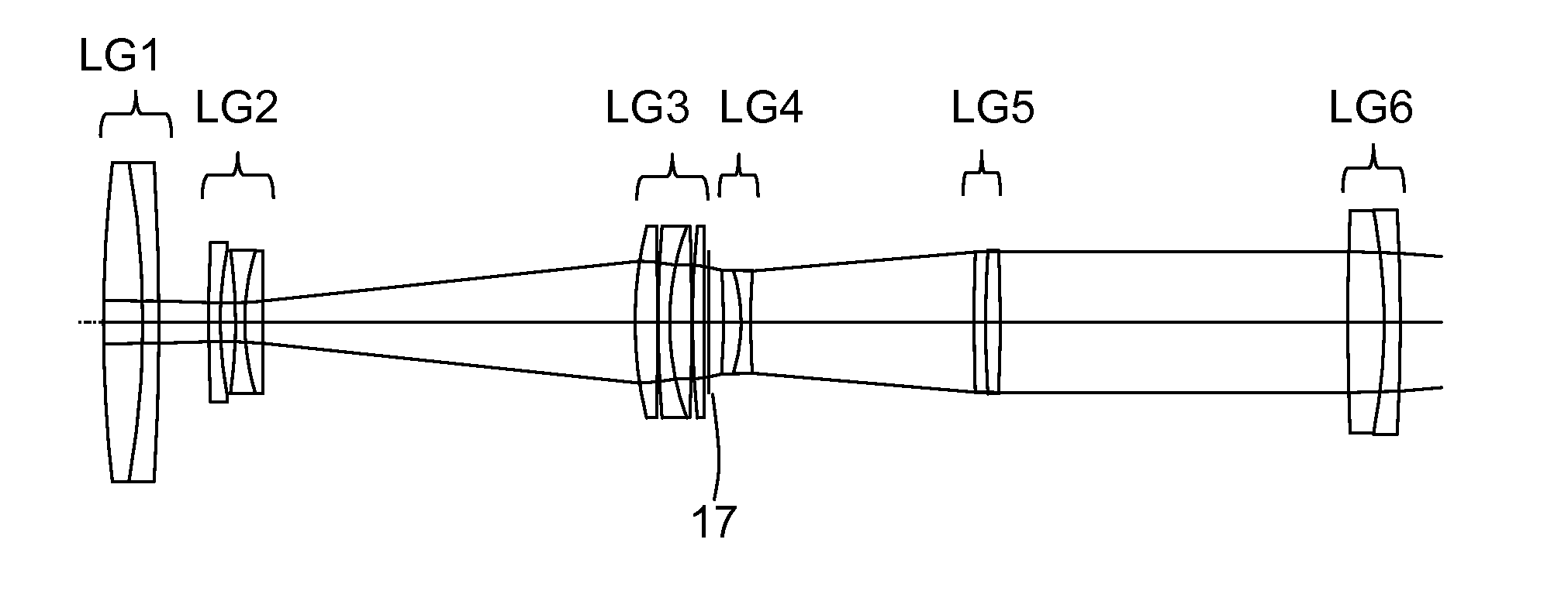
[0007]According to the invention, this problem is solved in such a way that[0008]the variation system consists of five lens groups and is designed to image the object into infinity,[0009]the lens group downstream of the variation system is intended for imaging the object from infinity into the image plane of the inspection system, and[0010]means for imaging the illuminating light into the exit pupil of the variation system are provided in the air space between the fifth lens group and the subsequent lens group.

[0011]Of the five lens groups of the variation system, the first, second and fourth lens groups (as seen in the imaging direction) are arranged so as to be movable along the optical axis, whereas the t...


PUM


Abstract

The invention relates to an optical inspecting system designed to image an object to be inspected with a variable imaging scale, comprising a variation system for imaging the object into infinity, a lens group downstream of the variation system for imaging the object from infinity into the image plane of the whole system, and a light source for generating light in order to illuminate the object, means for imaging the illuminating light into the exit pupil of the variation system being provided in the airspace between the fifth lens group and the subsequent lens group. Of the five lens groups of the variation system, the first, second, and fourth lens groups, when seen in the imaging direction, are arranged in a movable manner in the direction of the optical axis, whereas the third and fifth lens groups are not movable.

Description

PRIORITY CLAIM[0001]The present application is a National Phase entry of PCT Application No. PCT / EP2011 / 069508, filed Nov. 7, 2011, which claims priority from DE Application No. 10 2010 061 862.4, filed Nov. 24, 2010, said applications being hereby incorporated by reference herein in their entirety.FIELD OF THE INVENTION[0002]The invention relates to an optical inspection system, designed to image an object to be inspected with a variable imaging scale. It comprises a variation system consisting of several lens groups, a lens group downstream of the variation system for imaging the object into the image plane of the inspection system, and a light source for generating light in order to illuminate the object.DESCRIPTION OF PRIOR ART[0003]Optical inspection systems of this kind work fast and contact-free, and therefore are suitable especially for use in connection with digital image processing systems.[0004]Their capabilities are limited, however, if object details of special interest...

Claims


Application Information

Patent Timeline
Patent Type & Authority Patents(United States)
IPC IPC(8): G02B3/02G02B15/173G02B15/14G02B21/02G02B21/22G02B13/22
CPCG02B15/14G02B15/173G02B13/22G02B21/025G02B21/22G02B15/146
Inventor WARTMANN, ROLFWINKLER, KERSTINSPRENGER, JOERG
Owner CARL ZEISS MICROSCOPY GMBH
Why Eureka
Try Eureka