Plastic part punching machine

A technology for stamping machines and plastic parts, applied in the field of plastic parts stamping machines, can solve the problems of not being able to stamp multiple parts at the same time, the stamping cannot be aligned, and the stamping quality is affected, so as to improve the stamping quality, avoid misalignment, and prevent position changes. Effect

Inactive Publication Date: 2012-06-13
常州鑫鹏工具制造有限公司
View PDF10 Cites 5 Cited by
  • Summary
  • Abstract
  • Description
  • Claims
  • Application Information

AI Technical Summary

Problems solved by technology

[0002] When the existing plastic parts stamping machine stamps the plastic parts, it stamps one part at a time, and cannot stamp multiple parts at the same time, so that the stamping efficiency is reduced. At the same time, the stamping cannot be aligned during stamping. Affect stamping quality

Method used


Image

  • Plastic part punching machine
  • Plastic part punching machine
  • Plastic part punching machine

Examples


Embodiment Construction

[0014] The present invention will be further described below in conjunction with the drawings and specific embodiments.

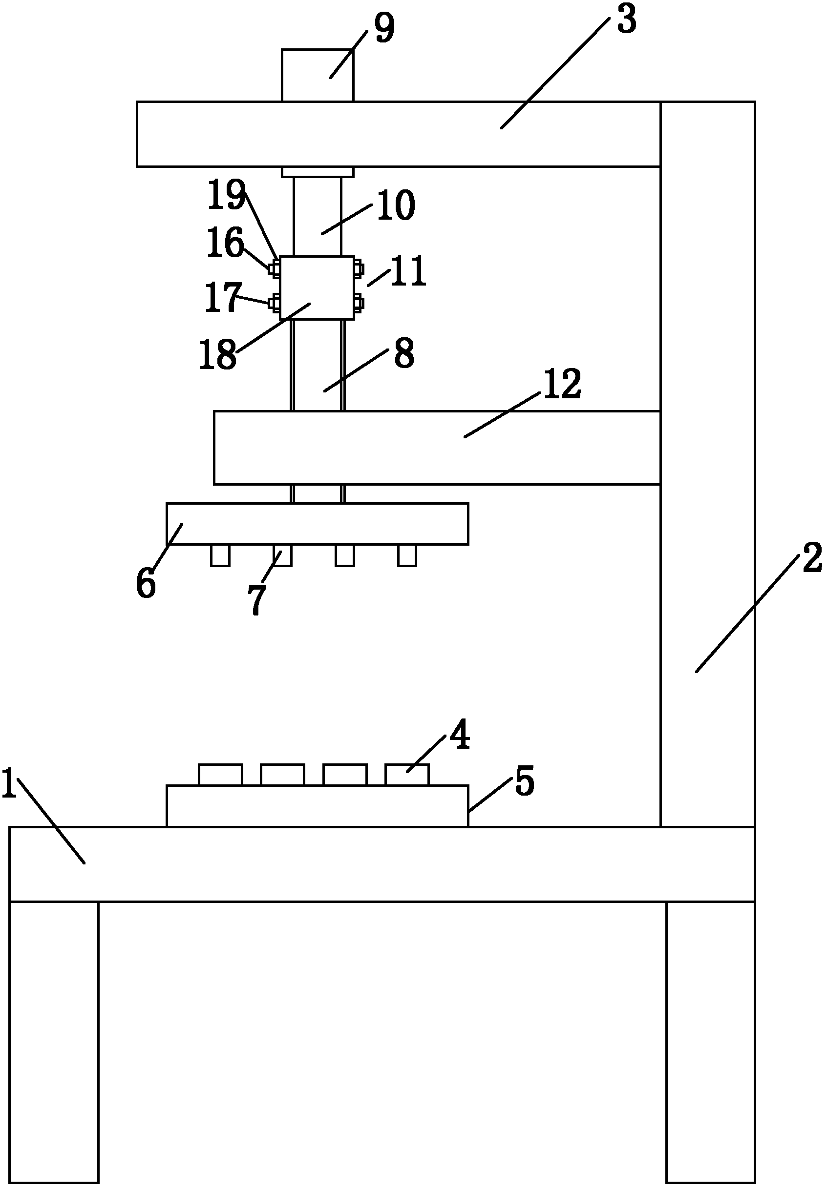
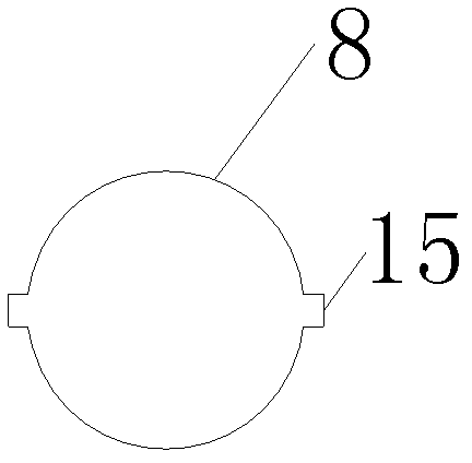
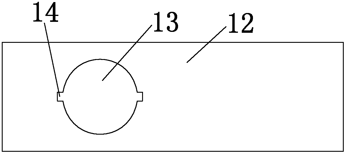
[0015] See figure 1 , 2 , 3, a plastic parts punching machine, the punching machine includes a lower base 1, a bracket 2 vertically arranged on the lower base, and an upper base 3 arranged on the upper end of the bracket, the upper end surface of the lower base is provided with a The lower punching plate 5 of a punching die 4 is provided with an upper punching plate 6 matching the punching plate under the upper base, and the lower end surface of the upper punching plate is provided with punching corresponding to the punching die on the lower punching plate. In the head 7, a guide rod 8 is fixed at the upper end of the upper punching plate, and a punch cylinder 9 is fixed under the upper base. The piston rod 10 of the punch cylinder and the guide rod 8 are fixedly connected by a connector 11. The bracket 2 is provided with a guide plate 12 for guiding the guide...


PUM


Abstract

The invention belongs to the technical field of punching machines, and particularly relates to a plastic part punching machine, which comprises a lower base, a support disposed vertically on the lower base and an upper base disposed at the upper end of the support. A lower punching disc provided with a plurality of punching dies is disposed on the upper end face of the lower base. An upper punching disc matched with a punching disc is disposed below the upper base. The lower end face of the upper punching disc is provided with punching heads which correspond to the punching dies on the lower punching disc one to one. A guide rod is fixedly arranged at the upper end of the upper punching disc, a punching cylinder is fixedly arranged below the upper base, and a piston rod of the punching cylinder is fixedly connected with the guide rod through a connector. During punching, a plurality of parts to be punched are correspondingly placed on the plurality of punching dies of the lower punching disc, the punching cylinder is started, the piston rod of the punching cylinder drives the upper punching disc downwards to enable the plurality of punching heads on the lower end face of the lower punching disc to correspond to the respective punching dies of the lower punching disc for punching, and accordingly a plurality of parts can be punched at one time and punching efficiency is improved.

Description

Technical field [0001] The invention belongs to the technical field of punching machines, and specifically relates to a plastic part punching machine. Background technique [0002] Existing plastic parts stamping machines are all stamping parts one part at a time. It cannot stamp multiple parts at the same time, which reduces the stamping efficiency. At the same time, the stamping cannot be aligned during stamping. Affect the quality of stamping. Summary of the invention [0003] In view of the above technical problems, the present invention provides a plastic part stamping machine, which can stamp multiple parts at a time and improve stamping efficiency. [0004] The technical scheme for realizing the present invention is as follows: [0005] A plastic parts punching machine includes a lower base, a bracket vertically arranged on the lower base, and an upper base arranged on the upper end of the bracket. The upper end of the lower base is provided with a plurality of punching dies....

Claims


Application Information

Patent Timeline
Patent Type & Authority Applications(China)
IPC IPC(8): B26F1/40
Inventor 金震宇
Owner 常州鑫鹏工具制造有限公司
Why Eureka
Try Eureka