Inclined core-pulling mechanism of injection mould spring sliding block

A spring-slider and oblique core-pulling technology, applied in the field of injection molds, can solve the problems of whitening, the trouble of setting the cooling water circuit of the core, and the increase of the injection mold volume.

Active Publication Date: 2014-02-26
ZHEJIANG KAIHUA MOLDS
View PDF5 Cites 9 Cited by
  • Summary
  • Abstract
  • Description
  • Claims
  • Application Information

AI Technical Summary

Problems solved by technology

[0002] After the plastic part is injection-molded by the injection mold, if there is an oblique hole on the plastic part, the prior art is to directly eject the plastic part vertically upwards by means of a ejector rod to force demoulding. If it is not consistent with the inclined direction of the inclined hole, the plastic parts are easily deformed, whitened, damaged during the forced removal process, and even cause the product to be scrapped
Another is to install an oil cylinder in the core. After the mold is opened, the oil cylinder firs

Method used


Image

  • Inclined core-pulling mechanism of injection mould spring sliding block
  • Inclined core-pulling mechanism of injection mould spring sliding block
  • Inclined core-pulling mechanism of injection mould spring sliding block

Examples


Embodiment Construction

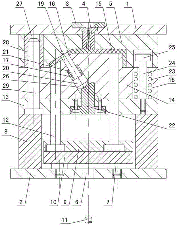
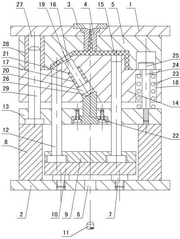
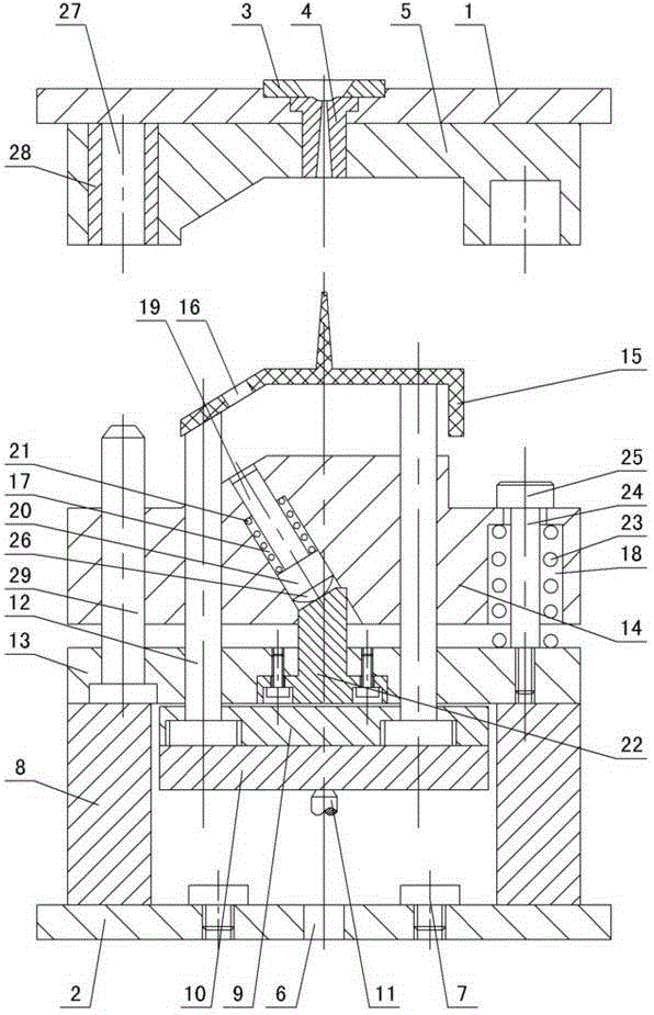
[0010] The invention relates to an oblique core-pulling mechanism for an injection mold spring slider, such as figure 1 — image 3 As shown, it includes an upper doubler plate 1 and a lower doubler plate 2, a positioning ring 3 and a gate bushing 4 are installed in the upper doubler plate, a cavity 5 is provided under the upper doubler plate, and a perforation 6 is opened in the lower doubler plate 2, The limit pin 7 and mold foot 8 are installed on the lower doubler plate, and the limit pin between the mold feet is provided with an upper ejector plate 9 and a lower ejector plate 10, and the ejector pin 11 of the injection machine passes through the perforation 6 and under the lower ejector plate 10 contact with each other, thimble 12 is installed between the upper and lower thimble plates, a support plate 13 is provided on the mold foot, a core 14 is provided on the support plate, and there is an injection-molded plastic part 15 between the core and the cavity 5, the plastic ...


PUM


Abstract

The invention discloses an inclined core-pulling mechanism of an injection mould spring sliding block. The inclined core-pulling mechanism comprises upper and lower compound plates, wherein a positioning ring and a sprue bushing are arranged in the upper compound plate; a cavity is arranged below the upper compound plate, a perforation is formed in the lower compound plate, and a limiting pin and mould feet are arranged on the lower compound plate; the mould feet are provided with upper and lower thimble plates, a push rod of an injection machine passes through the perforation so as to contact with the lower thimble plate, a thimble is arranged between the upper and lower thimble plates, a core is arranged on a supporting plate arranged on the mould feet, and a plastic piece is arranged between the core and the cavity; an inclined hole is formed in the plastic piece; the inclined core-pulling mechanism of an injection mould spring sliding block is characterized in that an inclined loose core groove and a spring groove are formed in the core, an inclined loose core is arranged in the inclined loose core groove, one end of the inclined loose core is provided with a stopper, and the outer wall of the inclined loose core is provided with an inclined loose core spring; one end of the inclined loose core spring is contacted with the bottom of the inclined loose core groove, the other end of the inclined loose core spring is contacted with the stopper, the supporting plate is internally provided with a tapered wedge, and the top of the tapered wedge is contacted with the stopper; the spring groove is internally provided with a spacing spring and a spacing pull nail, one end of the spacing pull nail is contacted with the top of the core, and the other end of the spacing pull nail passes through the core so as to be fixed with the supporting plate.

Description

technical field [0001] The invention relates to an injection mold, in particular to an oblique core-pulling mechanism of a spring slide block of an injection mold. Background technique [0002] After the plastic part is injection-molded by the injection mold, if there is an oblique hole on the plastic part, the prior art is to directly eject the plastic part vertically upwards by means of a ejector rod to force demoulding. If it is not consistent with the inclined direction of the inclined hole, the plastic parts are easily deformed, whitened, damaged during the forced removal process, and even cause the product to be scrapped. Another is to install an oil cylinder in the core. After the mold is opened, the oil cylinder first drives the oblique core to slide inward to pull the core, and then the ejector pin pushes the plastic part out. The disadvantage of this structure is that the oil cylinder is large in size and installed on Inside the core, the volume of the entire inje...

Claims


Application Information

Patent Timeline
IPC IPC(8): B29C45/33B29C45/40
CPCB29C45/33B29C45/40
Inventor 梁正华
Owner ZHEJIANG KAIHUA MOLDS
Why Eureka
Try Eureka