Filter-carrying micro plate

A filter and micro-plate technology, applied in the direction of fixed filter element filter, filtration separation, instrument, etc., can solve the problems of filter damage, assembly difficulty, sample backflow, etc., to achieve easy assembly, solve proficiency, prevent position effect of change

Inactive Publication Date: 2009-04-29
DAI NIPPON PRINTING CO LTD
View PDF2 Cites 4 Cited by
  • Summary
  • Abstract
  • Description
  • Claims
  • Application Information

AI Technical Summary

Problems solved by technology

Although these elements need to be assembled quickly and in a clean state, in these known microplates, the focus is mainly on the development of filters, and it is difficult to quickly and hygienically assemble the elements constituting the microplate
In addition, the microplate generally uses a very thin and easily broken filter. Therefore, during the movement of the microplate, the position of the filter changes from time to time, resulting in an accident of damage.
In addition, when filtering the substance to be inspected, depending on the content of the inspection, it is sometimes required that the mesh of the filter be formed very finely, but in this case, there is a problem that it takes a long time for the substance to be inspected to pass through the filter
Furthermore, in the case of microplates, it is very difficult to stack multiple microplates when multiple microplates are required to examine multiple specimens.
[0010] Moreover, the sample in the storage part may be mixed with the sample in the adjacent storage part during the inspection suction, and when a large negative pressure is applied during the inspection suction, the sample may flow backward. The problem that the sample may flow out of the storage part during suction

Method used


Image

  • Filter-carrying micro plate
  • Filter-carrying micro plate
  • Filter-carrying micro plate

Examples


Embodiment 1

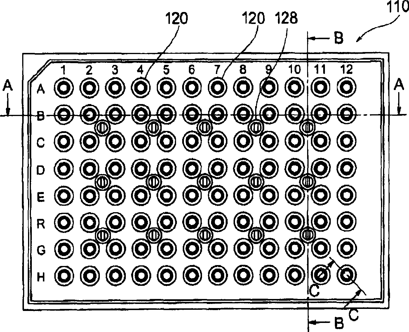
[0096] figure 1 It is an enlarged plan view showing a microplate 110 with a filter, which is an example of the device of the present invention. As shown in the drawing, the surface of the microplate has a rectangular shape, and the whole has, for example, a cuboid of about long side (120-150 mm)×short side (80-100 mm)×thickness (10-20 mm). However, it is obvious to those skilled in the art that the size and shape can be changed according to the application and other requirements. Therefore, the surface shape of the filter-attached microplate 110 of the present application may be, for example, a circle or an ellipse other than the illustrated rectangular shape and other rectangular shapes. However, in the following examples, the aforementioned rectangular microplates will be described. This microplate 110 is arranged with a plurality of (on figure 1 In the example, 12×8, a total of 96) openings 120, through which the culture solution (for example, a test substance such as co...

Embodiment 2

[0133] Figure 7 It is a plan view of the microplate 40 with a filter of the present invention. As shown in the drawing, the surface of the microplate 40 has a rectangular shape, and the whole has, for example, a cuboid of about long side (120-150 mm)×short side (80-100 mm)×thickness (10-30 mm). However, it is obvious to those skilled in the art that the size and shape can be changed according to the application and other requirements. Therefore, the surface shape of the microplate 40 with filter of the present application invention is except Figure 7 In addition to the illustrated rectangular shape and other rectangular shapes, for example, a circular or elliptical shape may also be used. However, in the following description, the above-mentioned rectangular microplate will be described. In this microplate 40, a plurality of (on Figure 7 In this example, 12×8, 96 in total) openings 50 , through which the culture solution (for example, the sample to be tested such as col...

Embodiment 3

[0174] The following will refer to Figure 41 Embodiment 3 of the invention of the present application will be described. Figure 41 The shown embodiment 3 is similar to the previously described embodiment 2, so only the parts different from the previously described embodiments will be mainly described below. exist Figure 41 In , elements or parts similar to those of the previous embodiments are denoted by appending A to the reference numerals of the previous embodiments. Additionally, from Figure 41 As can be seen in the illustrated embodiment, constituting Figure 41 elements of the previous drawings, especially Figure 9 The shown elements have slightly different shapes, but the basic structure of each element is basically the same as that of the previous embodiment, but it is a change that can be easily understood by those skilled in the art, so the description of each constitution of Embodiment 3 is omitted. A detailed illustration of the element.

[0175] exist F...


PUM


Abstract

There is provided a filter-equipped microplate including: an upper container 41 having openings 50 for injection of a substance to be tested; a top packing 44 and a bottom packing 45 that hold filters 46; a middle container 42 that fits with the upper container 41 and has openings 63 through which a test sample that has passed through the filters 46 runs, and that clamps the top packing 44 and the bottom packing 45 against the upper container 41: and a lower container 43 having reservoirs 80 that retain the test sample, the lower container 43 being held in a freely detachable manner against the middle container 42, wherein the middle container 42 has guide walls 64 that suspend down from the openings 63 and provide downward openings 65 to the bottom end, and the reservoirs 80 in the lower container 43 house the guide walls 64, the reservoirs 80 receiving the test sample supplied from the downward openings 65 of the guide walls 64 through the filters 46, and the lower container 43 having vents 90 at a widening slant 92 at the top, that communicate with the outside of the reservoirs 80.

Description

technical field [0001] The invention of the present application relates to a microplate with a filter. More specifically, it relates to a microplate incorporating a filter having a structure in which a substance to be tested passes through the filter, a filtered test sample is collected in a storage part, and the storage part can be easily separated . Microplates with filters are widely used in cell tissue culture or bioculture tissue inspection and other fields. Background technique [0002] In the microplate with a filter, components that hinder the detection sensitivity are separated from the test substance through the filter in advance, that is, filtered to obtain only the components that are useful for the desired culture purpose or test. This is because, when unnecessary components are mixed, there are problems in that excessively unwanted peaks appear, making it difficult to identify a targeted peak point, or that an originally intended peak point does not respond a...

Claims


Application Information

Patent Timeline
Patent Type & Authority Applications(China)
IPC IPC(8): G01N35/02B01D29/00B01D35/02C12N15/00G01N33/48G01N37/00
Inventor 植松裕德永智子竹居滋郎
Owner DAI NIPPON PRINTING CO LTD
Why Eureka
Try Eureka