Floor plate for covering a floor framework in an aircraft

a technology for aircraft floors and floor frameworks, which is applied in the direction of aircraft crew accommodation, transportation and packaging, fuselages, etc., can solve the problems of increasing installation and storage costs, difficult changes to the positioning of sub-assemblies on the floor of passenger cabins, and limited positioning of sub-assemblies on the floor frameworks

Active Publication Date: 2016-03-15
AIRBUS OPERATIONS GMBH
View PDF27 Cites 10 Cited by
  • Summary
  • Abstract
  • Description
  • Claims
  • Application Information

AI Technical Summary

Benefits of technology

[0013]As a result of this, a simple and especially positionally flexible connecting of a sub-assembly, which is arranged on the floor plate, to the supply infrastructure of the aircraft is provided. The system port which is integrated directly into the floor plate for example can be formed as double-ended or two-way electrical plug-in socket, wherein one plug-in socket is arranged in an upper side of the floor plate and a second plug-in socket can be arranged opposite this in an underside of the floor plate. Therefore, the sub-assembly, which is fastened on the floor plate, can be connected to the system port by means of simple tool-less plugging in of a sub-assembly connecting cable, which is provided with a corresponding plug, into the upper plug-in socket. The connecting of the system port to the electrical on-board system of the aircraft for example can be carried out by means of a supply cable which is led in on the underside, the (end) plug of which is plugged into the plug-in socket of the system port, which is arranged in the floor plate on the underside, from the bottom. Alternatively, the system port can also be designed as a two-way plug.
[0019]As a result of this, the installation effort which is required for connecting the sub-assembly to the on-board system of the aircraft is significantly reduced since the connecting of the sub-assembly to any on-board systems is carried out by means of for example snap-in plug-in connections inside the system port.

Problems solved by technology

At present, these sub-assemblies can only be fastened in the areas in which longitudinal profiles and / or transverse beams extend since a mechanical connection of the sub-assembly to the floor framework is made, as a result of which the positionability of the sub-assemblies on the floor framework is considerably limited.
The two aspects make any changes to the positioning of the sub-assemblies on the floor of the passenger cabin more difficult, as a result of which customer-specific equipping wishes or constructionally related changes of the installation point of the sub-assemblies are to be realized only at increased cost.
Furthermore, because of the reinforcing profiles which are to be provided during the interior equipping of the passenger cabin, the installation and storage cost is increased.

Method used


Image

  • Floor plate for covering a floor framework in an aircraft
  • Floor plate for covering a floor framework in an aircraft
  • Floor plate for covering a floor framework in an aircraft

Examples


Embodiment Construction

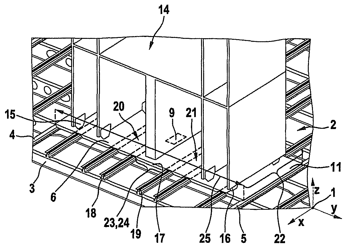
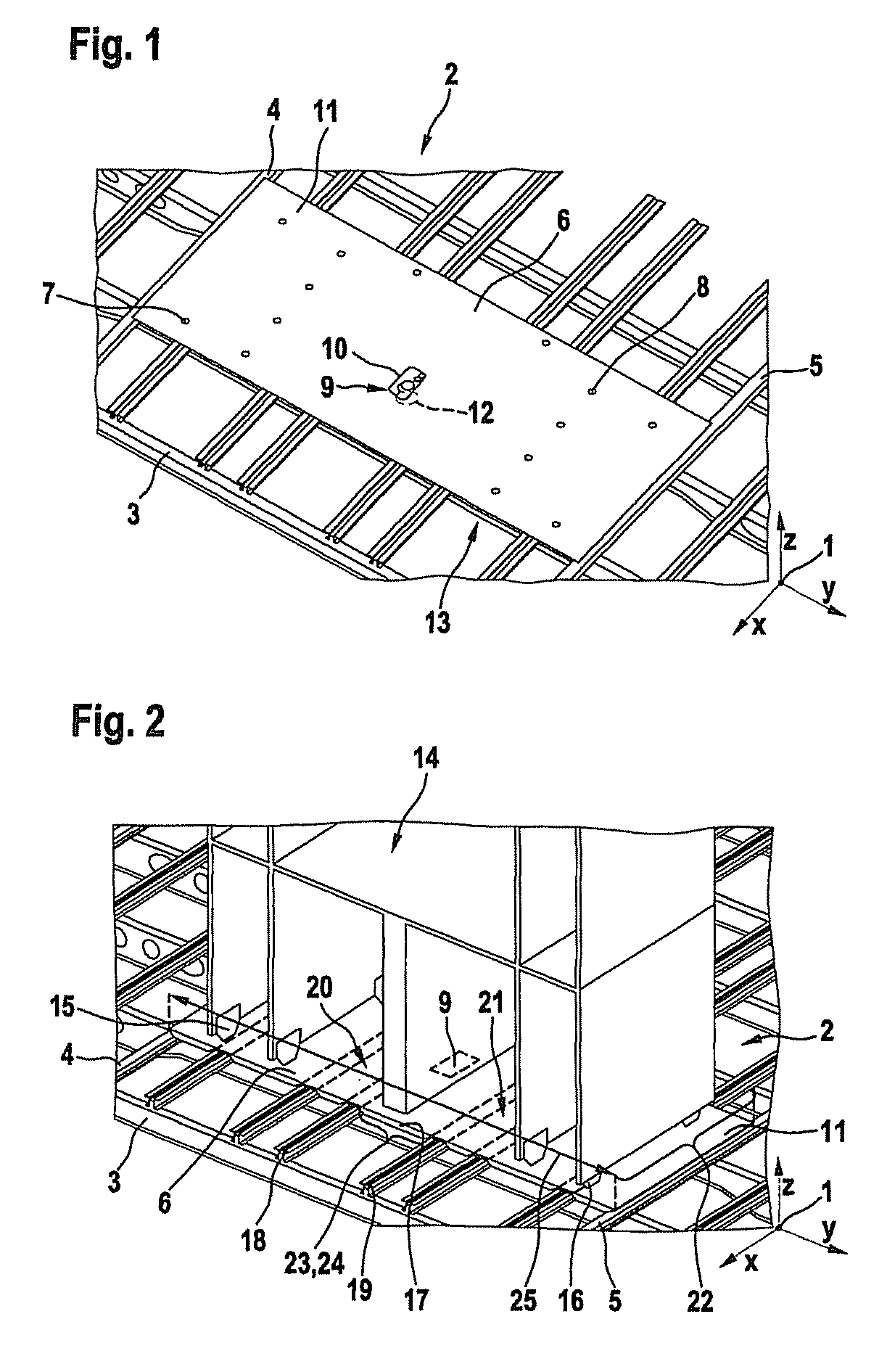
[0028]FIG. 1 shows a perspective view of a detail of a floor framework in an aircraft with a bearing floor plate, wherein the floor plate is provided with a system port.

[0029]A coordinate system 1 illustrates the position of all the components in space. A floor framework 2 of an aircraft, which is not shown, comprises inter alia a multiplicity of transverse beams which extend in a parallel spaced-apart manner, of which only one transverse beam 3 is provided with a designation, which is representative for the rest. All the transverse beams extend essentially parallel to the y-axis of the coordinate system 1 and are connected to other elements, which are not shown, of the fuselage cell structure of the aircraft, such as ring frames, samer rods, or the like. A multiplicity of seat rail profiles as longitudinal reinforcing elements bear upon the transverse beams 3, of which only two outer seat rail profiles 4, 5 are provided with a designation, which is representative for all further se...


PUM


Abstract

The invention relates to a floor plate for bearing upon a floor framework in an aircraft. The floor framework is formed with a multiplicity of transverse beams which are arranged like a truss, and a multiplicity of longitudinal profiles, especially seat rail profiles, which extend transversely to the transverse beam. At least one sub-assembly, for example a kitchen module and / or a sanitary cell, can be fastened on the floor plate. The floor plate bears upon at least four longitudinal profiles and has at least one connecting point, especially an insert, for fastening of the sub-assembly. In addition, at least one system port is provided for the tool-less, pluggable connecting of the sub-assembly to any on-board systems of the aircraft, especially to electrical systems, to feed-air systems, to exhaust air systems, to fresh-water systems or to waste-water systems.

Description

CROSS-REFERENCE TO RELATED APPLICATIONS[0001]This application claims priority to U.S. Provisional Application No. 61 / 009,311, filed Dec. 27, 2007.FIELD OF THE INVENTION[0002]The invention relates to a floor plate for covering a floor framework in an aircraft, wherein the floor framework is formed with a multiplicity of transverse beams and with a multiplicity of longitudinal profiles, especially seat rail profiles, which extend at an angle of about 90° to the transverse beams, wherein at least one sub-assembly can be fastened on the floor plate, and the floor plate can be connected with fastening devices, especially with screws and / or rivets, to the floor framework, especially to the longitudinal profiles.BACKGROUND OF THE INVENTION[0003]For creating a walkable floor, a floor framework is customarily arranged in the fuselage cell of an aircraft. The floor framework comprises a multiplicity of transverse beams which are arranged transversely to the direction of flight. A multiplicity...

Claims


Application Information

Patent Timeline
Patent Type & Authority Patents(United States)
IPC IPC(8): B64C1/18B64D11/00
CPCB64C1/18B64D2011/0046
Inventor KOOK, MANFREDSCHOPENHAUER, WOLFRAM
Owner AIRBUS OPERATIONS GMBH
Why Eureka
Try Eureka