Fast closing mechanism

a fast closing mechanism and circuit breaker technology, applied in the field of low voltage electrical equipment, can solve the problems of large closing arc, large opening structure of the mechanism, and influence on the life expectancy of the product, and achieve the effect of large initial speed

Active Publication Date: 2016-05-31
SEARI ELECTRIC TECH +1
View PDF11 Cites 0 Cited by
  • Summary
  • Abstract
  • Description
  • Claims
  • Application Information

AI Technical Summary

Benefits of technology

[0014]The fast closing mechanism according to the present invention has an additional ejector pin based on conventional structures. The press plate may press against a moving contact at an initial stage of a closing process, so that the moving contact will not move during the initial stage of the closing process. The mechanical energy generated during the closing process is stored in an energy storage spring. At a later stage of the closing process, the ejector pin releases the press plate, the press plate and the moving contact obtain a large initial speed by the spring force of the energy storage spring and accomplish closing quickly. The period for accomplishing the action of closing is reduced to 2-3 ms.

Problems solved by technology

Generally, such mechanisms have a fast opening structure because large break arc will be generated during an opening operation.
However, many of the mechanisms do not have a fast closing structure, then large arc generated during a closing process may burn and damage the contacts, which may influence the life expectancy of the products.
A slow closing process will result in a very large closing arc.
According to a high-speed photography based calculation, the “slow closing and fast opening” structure needs a period from several hundreds milliseconds to one second to accomplish the closing process, such a long period may result in closing arc that would be large enough to damage the mechanism.

Method used


Image

  • Fast closing mechanism
  • Fast closing mechanism
  • Fast closing mechanism

Examples


Embodiment Construction

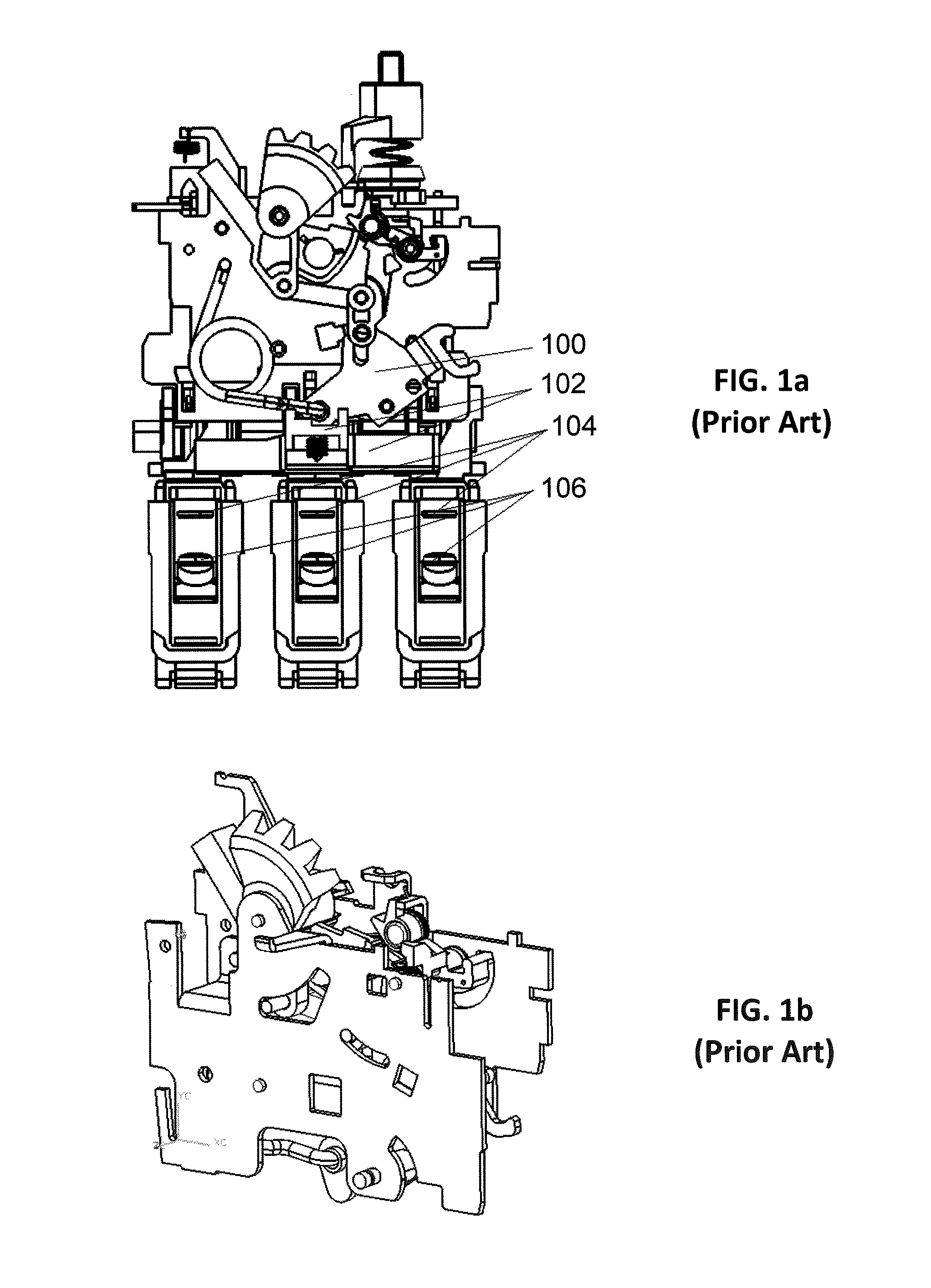
[0021]FIGS. 1a and 1b illustrate a prior art structure of a circuit breaker without a fast closing mechanism. The circuit breaker comprises a push rod 100, a press plate 102, a static contact 104 and a moving contact 106. FIG. 1a illustrates the front view of the structure of the circuit breaker. FIG. 1b illustrates the solid view of the structure of the circuit breaker. For the circuit breaker according to prior art, during a closing process, the push rod 100 is pulled and drive the press plate to raise, the moving contact 106 raises with the press plate 102 to accomplish closing. Pulling the push rod 100 is realized by manual operation and generally takes 0.5-1 second, or even longer. According to a high-speed photography based calculation, the prior art circuit breaker takes at least 300 ms to accomplish the closing process, and an average value is about 1 second. That means, during the closing process, closing arc with a duration of 1 second will be generated between the static ...


PUM


Abstract

A fast closing mechanism includes a rotation shaft and an ejector pin. The ejector pin is rotatably assembled to the side plate by the rotation shaft. The ejector pin strides over the side plate. The ejector pin includes a first portion and a second portion. The first portion is connected to a handle via a rod, and the second portion is located above a press plate. The fast closing mechanism may have an additional ejector pin based on current structures, the press plate may press against a moving contact at an initial stage of a closing process, so that the moving contact will not move during the initial stage of the closing process. The mechanical energy generated during the closing process is stored in an energy storage spring. At a later stage of the closing process, the ejector pin releases the press plate to accomplish closing quickly.

Description

CROSS REFERENCE TO RELATED APPLICATIONS[0001]This is a national stage application based on PCT / CN2012 / 082616, filed on Oct. 9, 2012, which claims priority to Chinese Patent Application No. 201110312440.7, filed on Oct. 14, 2011. This application claims the priority of these prior applications and incorporates their disclosures by reference in their entireties.BACKGROUND OF THE INVENTION[0002]1. Field of the Invention[0003]The present invention relates to low voltage electrical apparatus, more particularly, relates to fast closing mechanism for circuit breaker.[0004]2. The Related Art[0005]Regular motor protection circuit breakers or motor starters with a current level above 25 A are all operated by handles. When operated, the handle rotates in a forward direction means closing (switch on), and the handle rotates in a reverse direction means opening (switch off). Generally, such mechanisms have a fast opening structure because large break arc will be generated during an opening opera...

Claims


Application Information

Patent Timeline
Patent Type & Authority Patents(United States)
IPC IPC(8): H01H71/50H01H33/40H01H71/52
CPCH01H33/40H01H71/503H01H71/52H01H2300/046H01H71/56H01H71/50
Inventor JIANG, GUPINGGU, XIANGGU, HUIMINXU, WENLIANGBAI, JICHAO
Owner SEARI ELECTRIC TECH
Why Eureka
Try Eureka