Input device

a technology of input device and input gear, which is applied in the direction of mechanical control device, process and machine control, instruments, etc., can solve the problems of difficulty in stably switching the position of the operation element, trouble that the operator needs to perform a redundant operation to set the r gear position, and achieve the effect of large initial speed

Active Publication Date: 2018-12-27
PANASONIC CORP +1
View PDF0 Cites 16 Cited by
  • Summary
  • Abstract
  • Description
  • Claims
  • Application Information

AI Technical Summary

Benefits of technology

[0009]The present disclosure has been made in the above circumstances of the prior art, and an object of the disclosure is therefore to provide an input device capable of switching an operation member such as a movable knob stably to a stop target position intended by an operator even in a case that the operator moves the operation member in such a manner as to move it abruptly with fingertips to give it a large initial speed, and thereby enabling support of safe use of an operation target. The knob movement may be either straight, rotative or a combination of a straight movement and a rotative movement.

Problems solved by technology

However, in the prior art techniques as disclosed in WO2006 / 021198 A1 and WO2007 / 076814 A1, if an operator rotates the operation member such as a knob with, for example, finger tips in such a manner as to move it abruptly and strongly to give it an excessive initial speed, the following trouble may occur.
This means a problem that it is difficult to switch the position of the rotary knob stably to a stop target position intended by an operator.
This also means a problem that it is difficult to switch the position of the operation element stably to a stop target position intended by an operator.
Further, when plural positions for setting gear positions of a transmission of a vehicle are linearly disposed and the operator sets the gear position by performing a linearly back and forth movement of the operation member in order to alter the gear position other than performing a rotational operation of the operation member, the following trouble may happen.
The trouble that the operator needs to perform a redundant operation to set the R gear position may happen.

Method used


Image

  • Input device
  • Input device
  • Input device

Examples


embodiment 1

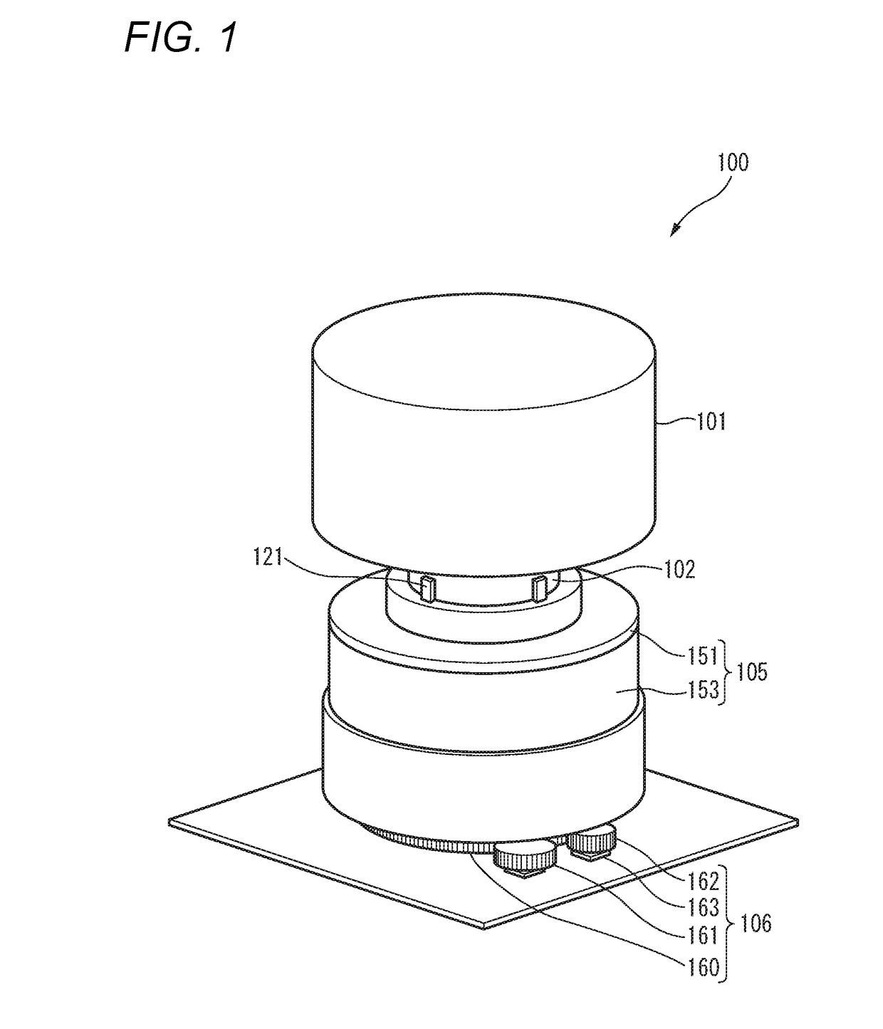
[0031]FIG. 1 is a perspective view of an input device 100 according to a first embodiment.

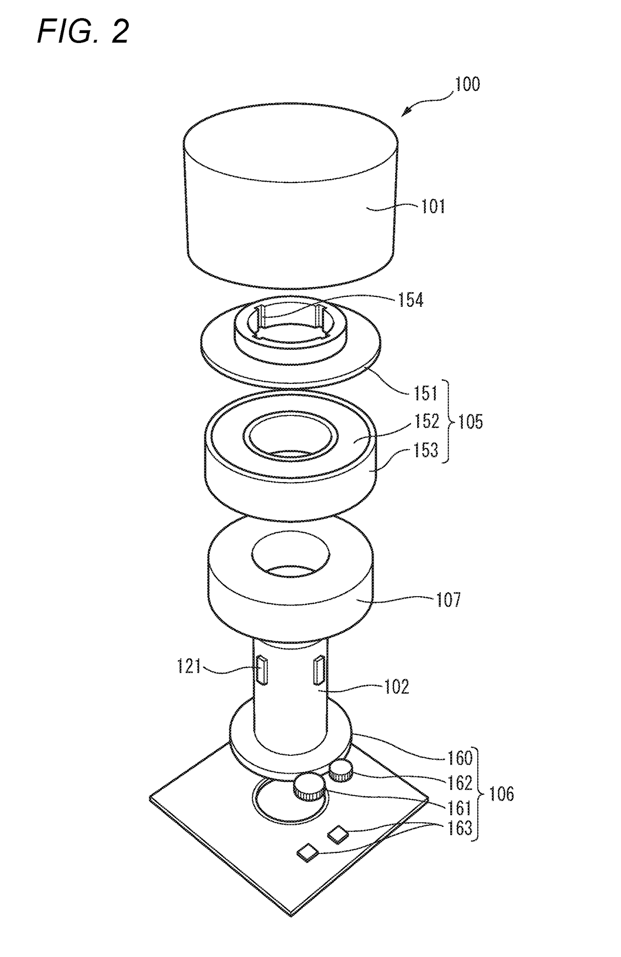
[0032]FIG. 2 is an exploded perspective view of the input device 100 according to the first embodiment.

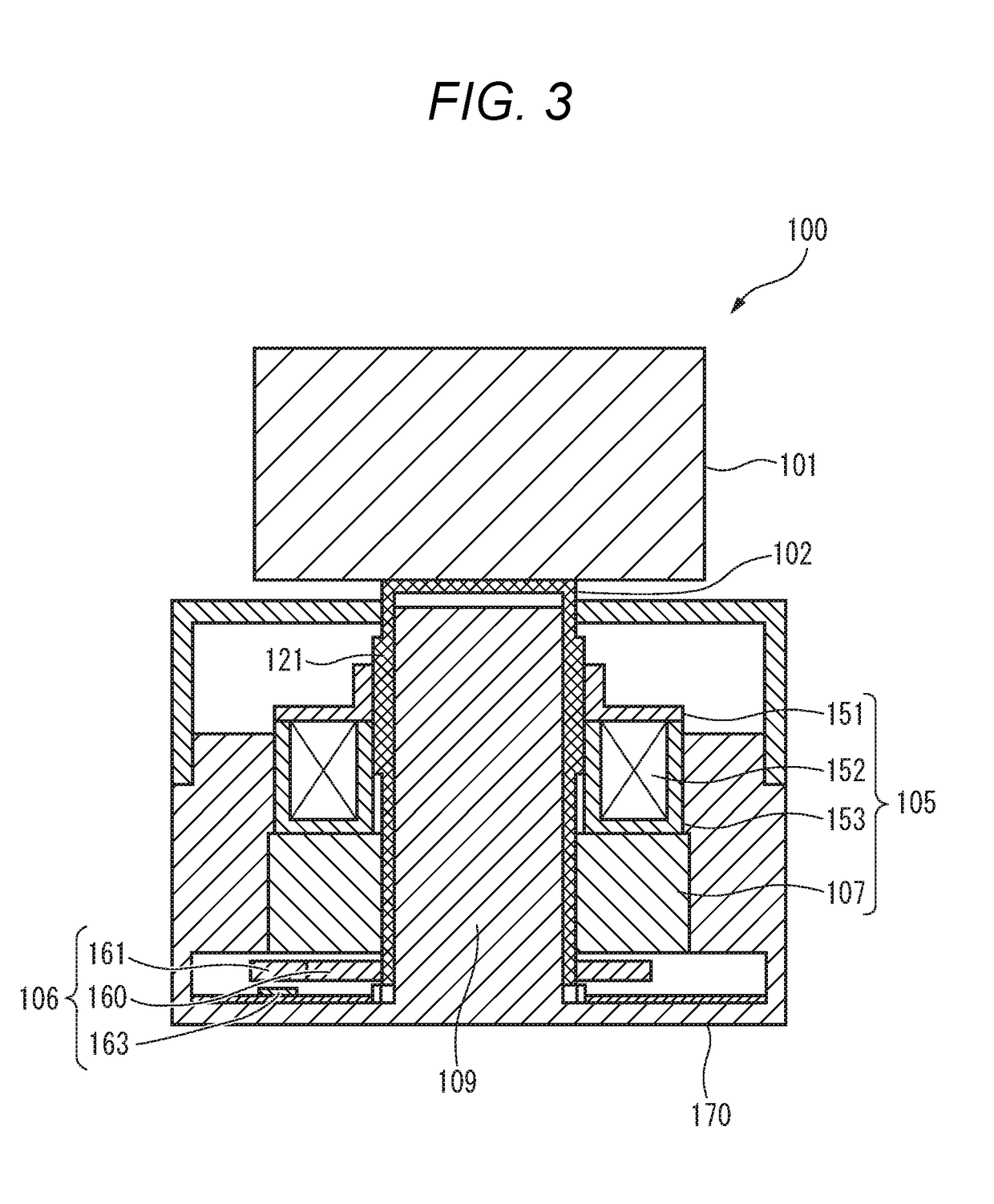
[0033]FIG. 3 is a sectional view illustrating an example of a cross section of the input device 100 according to the first embodiment.

[0034]FIG. 4 is a sectional view illustrating an example of an essential part of a mechanical detent mechanism DTM of the input device 100 according to the first embodiment.

[0035]FIG. 5 is a diagram illustrating an example of detent range Dtrg of the mechanical detent mechanism DTM of the input device 100 according to the first embodiment.

[0036]FIG. 6 is a block diagram illustrating an example of functional units and mechanical units of the input device 100 according to the first embodiment.

[0037]As shown in FIGS. 1-3 respectively, the input device 100 is a device capable of inputting a signal corresponding to a rotating operation made by, for example, a hand of...

embodiment 2

[0133]In the first embodiment, since the electromagnetic brake (i.e., rotation braking unit 105) exerts a braking force on the knob 101 according to a rotation speed of the knob 101 that is higher than the reference speed, the knob 101 is stopped at a current shift position or a shift position next to it. In this case, for example, it may be difficult for an operator to stop the knob 101 after rotating (moving) it from a current shift position (e.g., D gear position) to an end stop position (e.g., P gear position) past plural shift positions by a single rotating operation.

[0134]In view of the above, in an input device 100 according to the second embodiment, the knob 101 is rotated (moved) from a current rotation position to a stop end position by, for example, a single rotating operation made by an operator in such a manner that rotation of the knob 101 is continued utilizing inertia that depends on a rotation speed of the knob 101. The input device 100 according to the second embod...

embodiment 3

[0161]In an input device 100 according to a third embodiment, switching is made between the operation of the input device 100 according to the first embodiment and the operation of the input device 100 according to the second embodiment according to whether the vehicle in which the input device 100 is installed is running ordinarily or is in a low-speed state immediately before a stop. The input device 100 according to the third embodiment has the same internal configuration as the input devices 100 according to the first and second embodiments shown in FIG. 6. In the third embodiment, only differences in operation etc. from the first and second embodiments will be described mainly; descriptions of what are the same as in the first or second embodiment will be simplified or omitted.

[0162]FIG. 14 is a detailed flowchart illustrating an example of an operation procedure of the input device 100 according to the third embodiment.

[0163]The operation procedure illustrated by FIG. 14 will ...


PUM


Abstract

An input device is equipped with an operation member that is capable of performing an operation by a hand of an operator; a braking unit configured to brake a movement of the operation member; a speed determiner configured to determine a current speed of the operation member; and a controller configured to cause the braking unit to brake the movement of the operation member in response to the current speed of the operation member

Description

BACKGROUND OF THE INVENTION1. Field of the Invention[0001]The present disclosure relates to an input device which can operate an operation target such as an electronic apparatus or a vehicle when an operation member such as a knob is moved by a hand of an operator.2. Description of the Related Art[0002]Input devices are known which can perform an operation relating to a function or a movement of an operation target, such as an electronic apparatus or a vehicle, connected to a rotatable knob when the knob is appropriately rotated by, for example, a hand of an operator. For example, WO2006 / 021198 A1 and WO2007 / 076814 A1 are respectively proposed as the prior art relating to such input devices.[0003]WO2006 / 021198 A1 discloses an operation device for, for example, a shift-by-wire vehicular transmission. Stoppers are provided at two locations to restrict the rotation angle of a rotary knob as an example of an operation member and a vehicular automatic transmission is switched according t...

Claims


Application Information

Patent Timeline
Patent Type & Authority Applications(United States)
IPC IPC(8): F16H61/24F16H59/08
CPCF16H61/24F16H2061/243F16H2059/081F16H59/08B60K20/02B60K20/08G05G1/08G05G5/03G05G1/015
Inventor YAMANAKA, SEIGODANIS, DAVID TUSETMULLET, NARCIS PALLARES
Owner PANASONIC CORP
Why Eureka
Try Eureka