Micromechanical component and method for producing a micromechanical component

a micromechanical and mirror technology, applied in the field of micromechanical components, can solve the problems of limiting the maximum mirror surface of the mirror segment, saving costs, etc., and achieve the effect of reducing costs and improving accuracy of measuremen

Active Publication Date: 2016-06-07
ROBERT BOSCH GMBH
View PDF5 Cites 0 Cited by
  • Summary
  • Abstract
  • Description
  • Claims
  • Application Information

AI Technical Summary

Benefits of technology

[0005]The recognition on which the present invention is based is that piezoelectric strips that are connected to a micromechanical plate spring and to which a voltage is applied, in particular an alternating voltage, can cause an elastic deformation of the plate spring. The basic idea of the present invention is to fashion a micromechanical component in such a way that a mirror element can be displaced by the elastic deformation of the plate spring, the mirror element being situated on the front side of the plate spring. In this way, it is possible to rotate even mirror elements having a large reflecting surface, largely without dynamic inherent deformation. For example, the reflecting surface can be 3.5 mm2 or more, while the dynamic inherent deformation of the reflective surface can at the same time be for example less than 10% of wavelengths of visible light, or can be less than 0.1 μm.
[0006]In this way, the micromechanical mirror can be driven in a resonant fashion in a very efficient and precise manner. That is, the elastic deformation of the plate spring can be realized through alternating current excitations that take place with a resonance frequency. In this way, significantly greater deformations can be achieved than can be achieved using static effects. The resonance frequencies of the plate spring and the mode spectrum of the modes of oscillation here are a function of the particular realization of the plate spring and of the elements connected thereto.
[0007]With the use of piezoelectric strips for the displacement of the functional element, the energy yield can be approximately 90%, because significantly less Joule heating can be produced in comparison with, for example, a magnetic drive. In addition, through the use of the piezoelectric strips a particularly small, and therefore low-cost, design can be realized.

Problems solved by technology

In such optical scanners, the maximum mirror surface of the mirror segment can be limited due to dynamic inherent deformations that result from the increasing moment of inertia of the mirror surface at a high resonance frequency.
In addition, production in this manner can save costs.

Method used


Image

  • Micromechanical component and method for producing a micromechanical component
  • Micromechanical component and method for producing a micromechanical component
  • Micromechanical component and method for producing a micromechanical component

Examples


Embodiment Construction

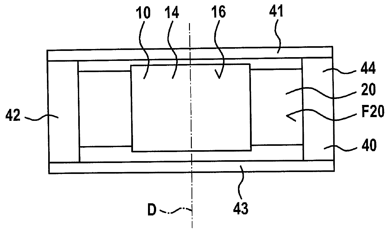
[0031]FIG. 1A shows a schematic top view from the front of a micromechanical component according to a first specific embodiment.

[0032]The component has a frame 40 that according to FIG. 1A is fashioned as a rectangular frame 40 having four first through fourth partial segments 41, 42, 43, 44 of frame 40. First and third partial segments 41, 43 are situated opposite one another and are fashioned parallel to one another, having the same dimensions. Second and fourth partial segments 42, 44 are also situated in parallel opposite one another and are fashioned essentially with the same dimensions. It is to be noted that frame 40 can also assume any other useful shape, for example an oval shape or a rectangular shape having different dimensions of first through fourth segments 41, 42, 43, 44.

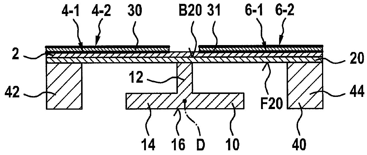
[0033]A plate spring 20 is connected to frame 40. The plate spring is fashioned essentially as a rectangular strip, i.e. as a flat cuboid. Plate spring 20 has a front side F20 that is a largest side s...


PUM


Abstract

A micromechanical component and a method for producing a micromechanical component are described. The component has: a frame; a plate spring that is connected to the frame and that has a front side and a rear side facing away from the front side; a mirror element that is situated on the front side of the plate spring and is connected to the front side of the plate spring in such a way that the mirror element is suspended on the frame so as to be capable of displacement; and at least one piezoelectric strip that is connected to the rear side of the plate spring; the plate spring being elastically deformable through the application of an electrical voltage to the at least one piezoelectric strip in order to displace the mirror element.

Description

FIELD OF THE INVENTION[0001]The present invention relates to a micromechanical component, in particular a micromechanical mirror, and to a method for producing a micromechanical component, in particular a micromechanical mirror.BACKGROUND INFORMATION[0002]Micromechanical mirrors are suitable for a large number of applications, for example microprojectors or lidar devices.[0003]In United States Published Patent Appln. No. 2011 / 0002022, a method is described for adapting a resonance frequency of an optical scanner. In this document, an optical scanner is described that has a main substrate body having two cantilevers, a drive device, a mirror segment, and a clamping device. The mirror segment is structured out from the main substrate body and is suspended between the two cantilevers. The mirror segment can be displaced relative to the clamping device by exciting the main substrate body with a resonance frequency. The resonance frequency is adapted through constructive modifications of...

Claims


Application Information

Patent Timeline
Patent Type & Authority Patents(United States)
IPC IPC(8): G02B26/08G02B26/10
CPCG02B26/0858
Inventor ARMBRUSTER, SIMONGRUTZECK, HELMUTSCHATZ, FRANKMUCHOW, JOERGNJIMONZIE, FREDERIC NJIKAMBAADER, JOHANNESDOESSEL, KERRINSTRAUB, RAINER
Owner ROBERT BOSCH GMBH
Why Eureka
Try Eureka