Tool set and bar for a knitting machine

Active Publication Date: 2008-11-13
GROZ BECKERT KG
View PDF11 Cites 0 Cited by
  • Summary
  • Abstract
  • Description
  • Claims
  • Application Information

AI Technical Summary

Benefits of technology

[0015]However, it is also possible to assign, to the holding parts of the tools of the two different types on the bar respectively their own cutouts, said cutouts being offset relative to each other in longitudinal direction of the tools. For example, the tools of the one type have a greater height on a front holding part section, whereas the holding parts of the tools of the second type have a greater height on a rear section. The bar is provided, for the holding parts of the tools of the first type, with a first row of cutouts and, for the accommodation of the holding parts of the tools of the second type, with a second row of cutouts. Then, the two rows of cutouts are offset with respect to each other, for example, by the dividing measure in longit

Problems solved by technology

The strips that limit the grooves for the accommodation of the holding parts are also very thin.
With increasing fineness, this initially leads to manufactu

Method used


Image

  • Tool set and bar for a knitting machine
  • Tool set and bar for a knitting machine
  • Tool set and bar for a knitting machine

Examples


Example

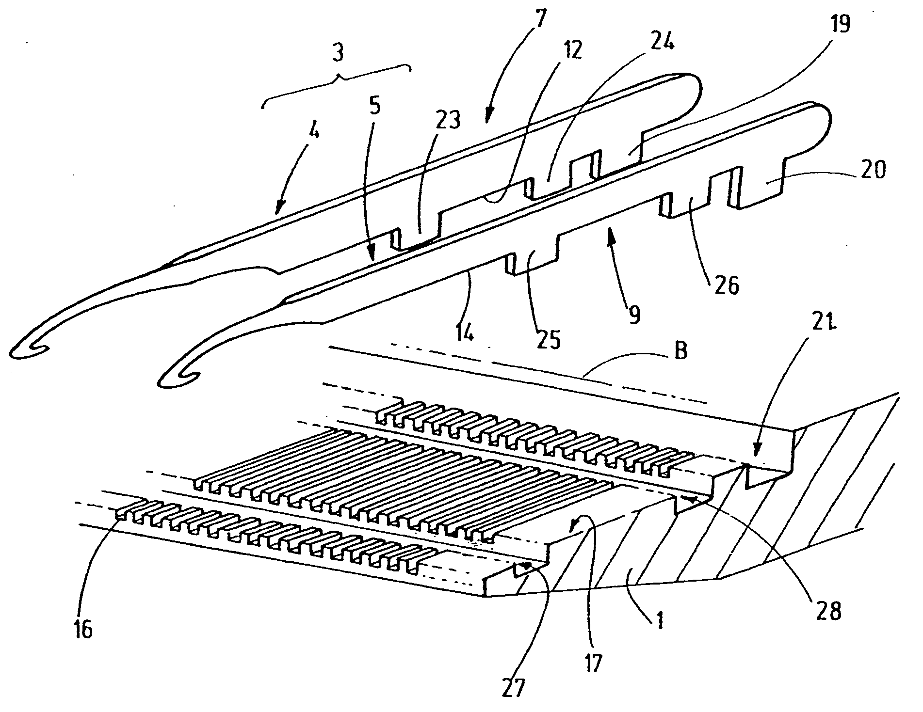
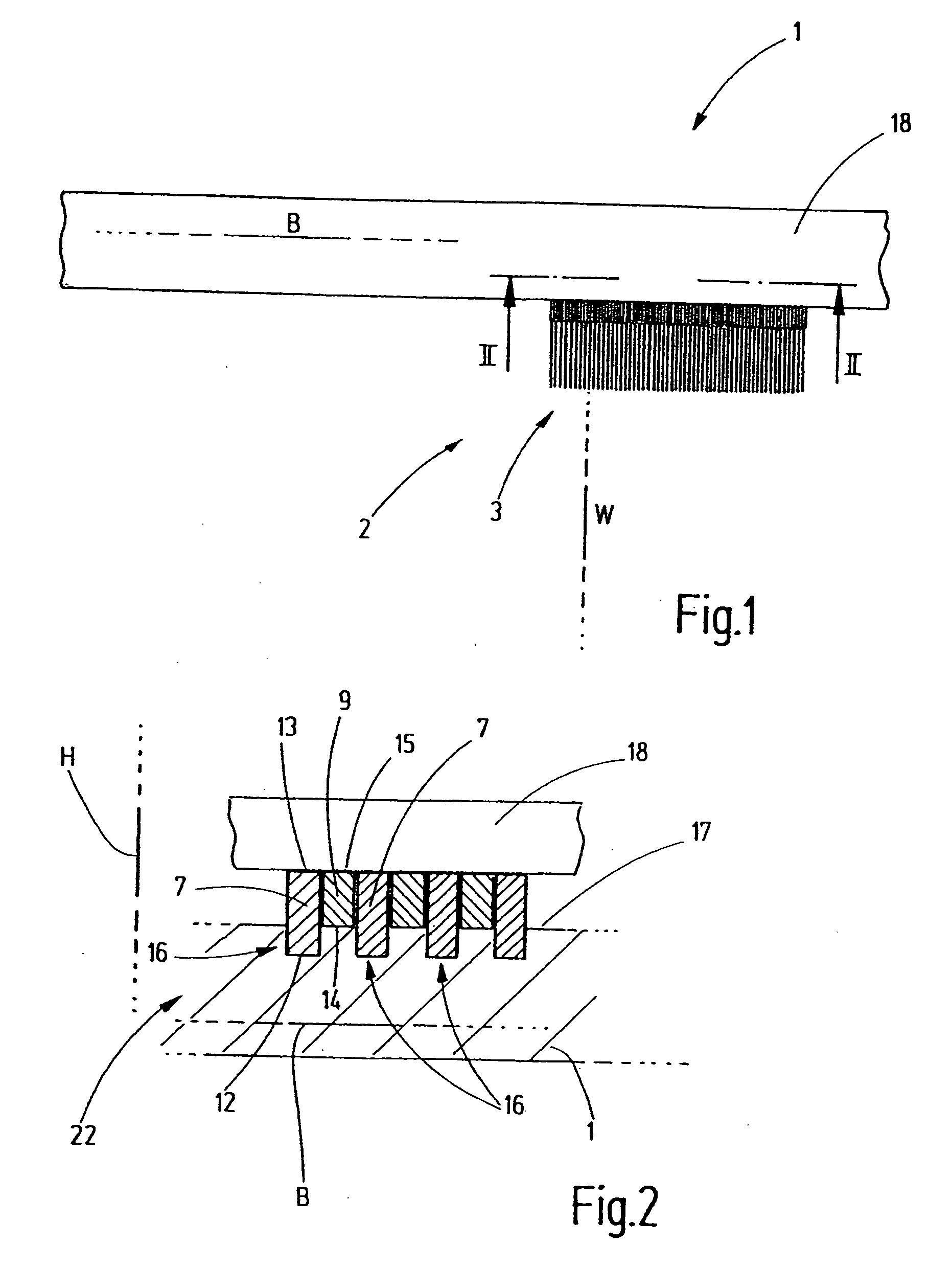
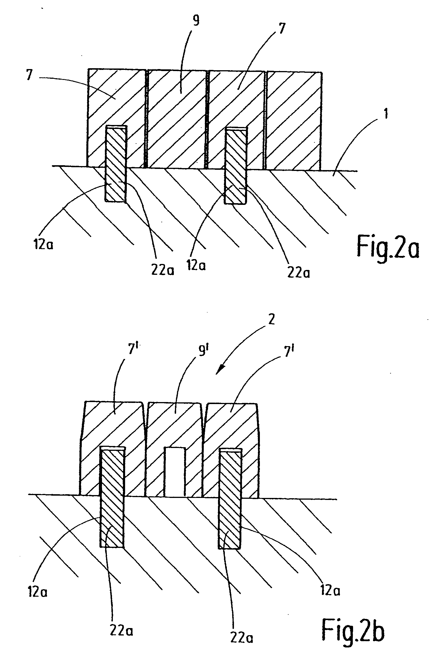
[0028]FIG. 1 shows a bar 1 which belongs to a knitting machine. The bar holds a number of tools 2 that are arranged in a row next to each other along the longitudinal direction B of the bar. In so doing, each of the tools 2 has a longitudinal direction W that is oriented in a direction transverse to the longitudinal direction B. The tools 2 are, for example, knitting tools in the form of knitting needles, sliders, needles with holes, knives or the like. They are used for the production of knit goods in textile production. The tools 2 form a tool set 3 that comprises a number of tools 4 of a first type and a number of tools 5 of a second type, as is obvious from FIG. 3. Each of the tools of the first type 4 has a working part 6 and a holding part 7. Each of the tools 5 of the second type has a working part 8 and a holding part 9. The working parts 6, 8 preferably match. Consequently, a uniform contour is formed on the bar 1. If the working parts 6, 8, for example, have hooks 10, 11 o...


PUM


Abstract

To simplify the setup of a bar and associated tools of a knitting machine and to improve the degree of precision regarding fineness and the level of sturdiness of the tools and bar system, the holding parts (7, 9) of the tools (4, 5) of the tool set (2) are configured differently. On the holding parts (7) of at least one tool type, means (22) are provided for positioning the tools (4) on the bar and thus means for defining the division. Separate positioning means for positioning and defining the division may be assigned to the other tools (5). Alternatively, they may be positioned by the tools (4) of the first type, between which they are accommodated. If positioning grooves are provided in the bar or parts thereof, these grooves may be set up for twice the distance of division, which results in robust and mechanically stable solutions with finer divisions.

Description

CROSS REFERENCE TO RELATED APPLICATION[0001]This application claims the priority of European Patent Application No. 07 008 922.2, filed on May 3, 2007, the subject matter of which, in its entirety, is incorporated herein by reference.BACKGROUND OF THE INVENTION[0002]The invention relates to a tool set for loading a bar of a knitting machine, as well as to a bar that is set up for the accommodation of tools, in particular the tool set in accordance with the invention.[0003]The bar of a knitting machines holds a large number of tools such as, for example, needles, sliders or the like, that are accommodated so as to be aligned parallel to each other at pre-specified distances. When the bar is moved, all the tools perform the same movement. The tools are mounted to the bar at fixed distances from each other. Usually, the distances are pre-specified by grooves that are machined parallel to each other in the bar and accommodate the holding parts of the tools.[0004]The measure for division...

Claims


Application Information

Patent Timeline
IPC IPC(8): D04B11/00D04B35/02
CPCD04B27/06D04B37/06D04B15/20D04B15/00
Inventor JURGENS, ERICDIETZ, ANDREASBUTZ, TORSTENKIRCHMAIR, KLAUS
Owner GROZ BECKERT KG
Why Eureka
Try Eureka