System, method, and apparatus for monitoring, regulating, or controlling fluid flow

a technology of system and method, applied in the direction of diaphragm valve, programme control, instruments, etc., can solve the problem that the pump cannot be used in all situations or environments, and achieve the effect of reducing the internal volume of the fluid tub

US9372486B2Active Publication Date: 2016-06-21DEKA PROD LLP
355 Cites 128 Cited by

Patent Information

Authority / Receiving Office
US · United States
Patent Type
Patents(United States)
Current Assignee / Owner
Publication Date
2016-06-21

Smart Images

  • Figure 1
    Figure 1
  • Figure 2
    Figure 2
  • Figure 3
    Figure 3
Patent Text Reader

Abstract

A flow meter, and related system and method are provided. The flow meter includes a coupler, a support member, an image sensor, a valve, and one or more processors. The coupler is adapted to couple to a drip chamber. The support member is operatively coupled to the coupler. The image sensor has a field of view and is operatively coupled to the support member. The image sensor is positioned to view the drip chamber within the field of view. The one or more processors are operatively coupled to the image sensor to receive image data therefrom and to the actuator to actuate the valve. The one or more processors are configured to estimate a flow of fluid through the drip chamber and to actuate the valve to control the flow of fluid through the drip chamber to achieve a target flow rate.
Need to check novelty before this filing date? Find Prior Art

Description

CROSS REFERENCE TO RELATED APPLICATIONS

[0001] The present application is a Non-Provisional Application which claims priority to and the benefit of the following:

[0002] U.S. Provisional Patent Application Ser. No. 61 / 679,117, filed Aug. 3, 2012 and entitled System, Method, and Apparatus for Monitoring, Regulating, or Controlling Fluid Flow; and

[0003] U.S. Provisional Patent Application Ser. No. 61 / 651,322, filed May 24, 2012 and entitled System, Method, and Apparatus for Electronic Patient Care, both of which are hereby incorporated herein by reference in their entireties.

[0004] This application claims priority to and is also a Continuation-In-Part Application of the following:

[0005] U.S. patent application Ser. No. 13 / 333,574, filed Dec. 21, 2011 and entitled System, Method, and Apparatus for Electronic Patient Care, now U.S. Publication No. US-2012-0185267-A1, published Jul. 19, 2012, and

[0006] PCT Application Serial No. PCT / US11 / 66588, filed Dec. 21, 2011 and entitled System, Method, an...

Examples

Embodiment Construction

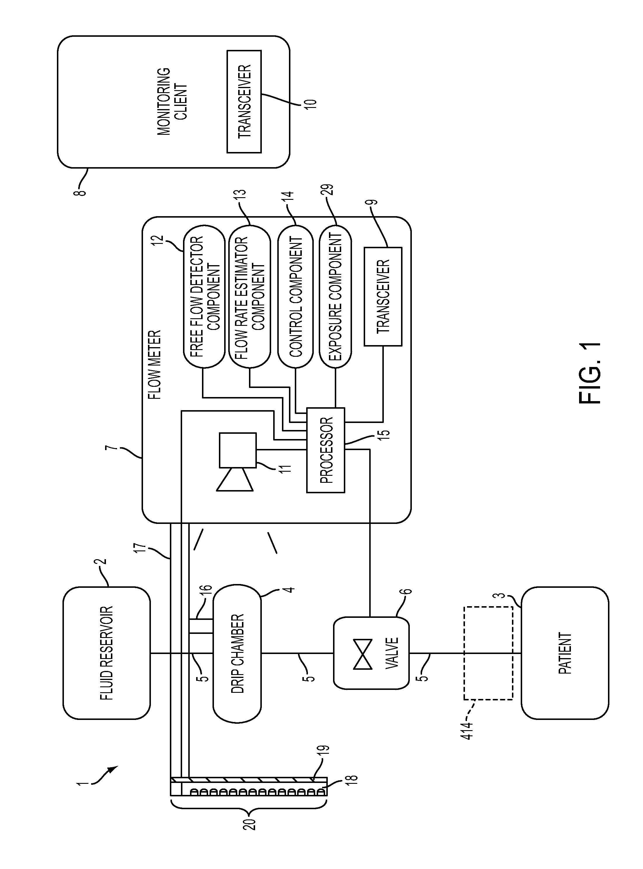
[0405]FIG. 1 shows a block diagram of a system 1 for regulating fluid flow in accordance with an embodiment of the present disclosure. For example, system 1 may regulate, monitor, and / or control the flow of fluid into a patient 3. The system 1 includes a fluid reservoir 2 for infusing fluid contained therein into the patient 3. The fluid reservoir 2 is gravity fed into a drip chamber 4 via a fluid tube 5. The fluid reservoir 2, the drip chamber 4, and the patient 3 may be considered as part of the system 1 or may be considered as separate or optional work pieces for the system 1 (e.g., any fluid reservoir 2 and drip chamber 4 may be used to treat any patient 3).

[0406]A flow meter 7 monitors the drip chamber 4 to estimate a flow rate of liquid flowing through the drip chamber 4. The fluid from the drip chamber 4 is gravity fed into a valve 6. The valve 6 regulates (i.e., varies) the flow of fluid from the fluid reservoir 2 to the patient 3 by regulating fluid flow from the drip chamb...