Fluid flow mixer

Active Publication Date: 2016-07-12
INNOVA GLOBAL LTD
View PDF45 Cites 5 Cited by
  • Summary
  • Abstract
  • Description
  • Claims
  • Application Information

AI Technical Summary

Problems solved by technology

Since simple ejection of the agent from such holes is not very effective in thoroughly mixing the agent with the fluid, it is also known to use baffles (sometimes also referred to as “deflectors” and “flow mixers”), usually positioned directly downstream of the injection point to encourage turbulence, thereby enhancing the mixing of the agent with the fluid.

Method used


Image

  • Fluid flow mixer
  • Fluid flow mixer
  • Fluid flow mixer

Examples


Embodiment Construction

[0021]The detailed description set forth below in connection with the appended drawings is intended as a description of various embodiments of the present invention and is not intended to represent the only embodiments contemplated by the inventor. The detailed description includes specific details for the purpose of providing a comprehensive understanding of the present invention. However, it will be apparent to those skilled in the art that the present invention may be practiced without these specific details.

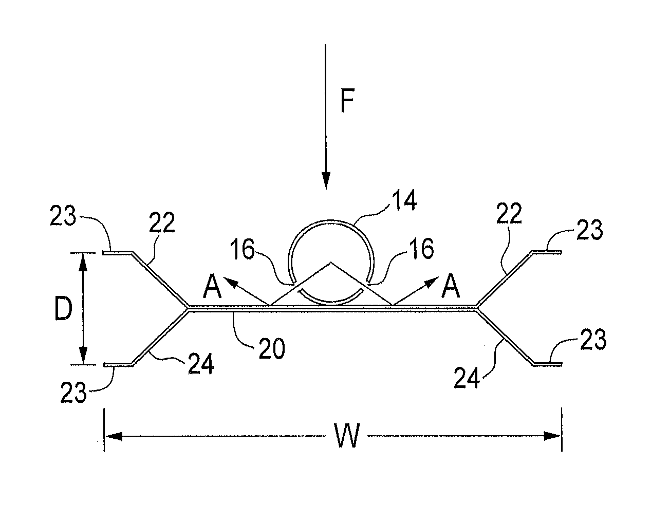
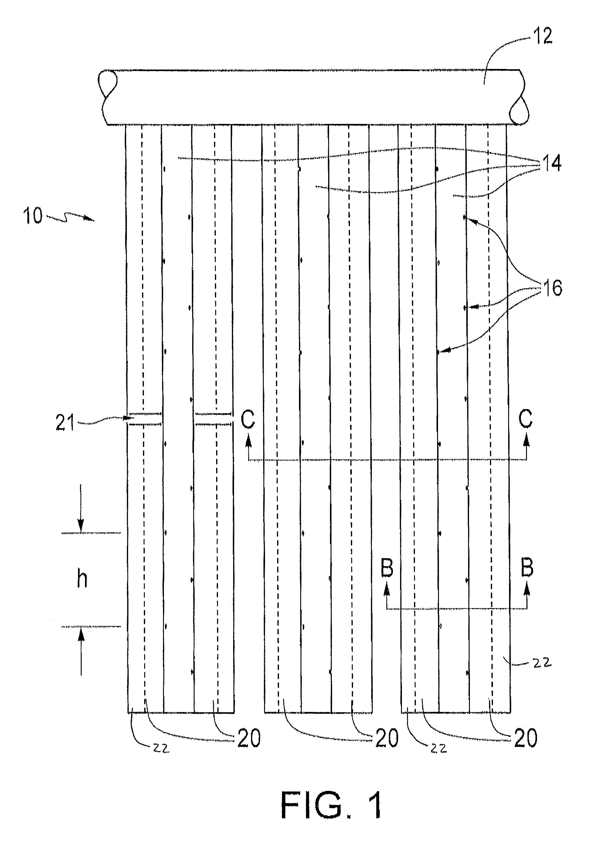
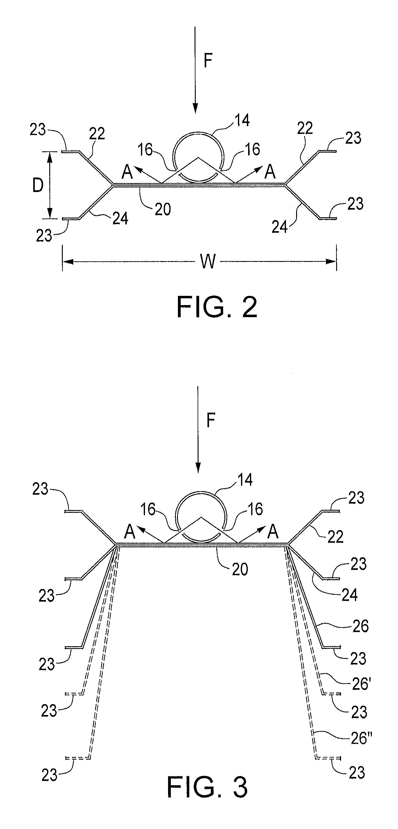
[0022]FIG. 1 shows a treating agent injection apparatus 10 comprising a manifold 12 and pipes 14 each having a plurality of holes 16. Manifold 12 is in fluid communication with the pipes 14 for supplying treating agent, such as diluted ammonia, from a vaporizer or heater (not shown) to each of the holes 16. Flow mixers 20 are associated with at least some of pipes 14. Apparatus 10 is installed in a flue and flue gas passes thereby between pipes 14 and flow mixers 20. Apparatu...


PUM

PropertyMeasurementUnit
angleaaaaaaaaaa
angleaaaaaaaaaa
angleaaaaaaaaaa

Abstract

An apparatus is provided for injecting and mixing a treating agent into a fluid stream. The apparatus comprises at least one pipe having a treating agent flowing therethrough. A flow mixer having a planar middle section with two furcated sides is disposed along the length of the pipe. Each furcated side may include at least two branches, each of which may have a flattened outer edge. The pipe has holes that may inject the treating agent towards the planar middle section. Adjacent flow mixers are separated by a distance. As fluid flows into and past the flow mixers, the injected treating agent is mixed with the fluid stream and the mixing is enhanced in turbulent mixing zones in between the flow mixers.

Description

FIELD[0001]This invention relates generally to an apparatus for fluid treatment, and more particularly relates to an apparatus for injecting a treating agent into a fluid stream while generating enhanced fluid phase turbulence to better distribute and mix the injected treating agent into the fluid.BACKGROUND[0002]During the course of treating a fluid, for instance to control the atmospheric emission of polluting contaminants, it is common to disperse a treating agent into the fluid in order to combine with a catalyst to treat the undesired component of the fluid. In general, a mixing apparatus is used to disperse the treating agent into the fluid. Holes, which include hardened holes, holes, nozzles, injection nozzles, and the like, can be used for this purpose. Since simple ejection of the agent from such holes is not very effective in thoroughly mixing the agent with the fluid, it is also known to use baffles (sometimes also referred to as “deflectors” and “flow mixers”), usually p...

Claims


Application Information

Patent Timeline
Patent Type & Authority Patents(United States)
IPC IPC(8): B01F5/06B01F5/04B01F3/04B01D53/86B01D53/90
CPCB01F5/0618B01D53/8631B01D53/90B01F3/04049B01F5/0451B01F5/0456B01F5/0463B01D2251/2062B01D2258/0283B01F23/2132B01F25/3131B01F25/31322B01F25/31331B01F25/4316
Inventor IVANOVA, VALENTINAWIRT, JEFFREY PHILIP
Owner INNOVA GLOBAL LTD
Why Eureka
Try Eureka