
Single-trigger clamping and firing of surgical stapler

a single-trigger, surgical stapler technology, applied in the field of surgical instruments, can solve the problems of increasing the complexity of use, the part count of surgical staplers, and the size of surgical staplers, and achieve the effect of increasing the complexity of use, the size of surgical staplers, and the number of parts

Active Publication Date: 2016-08-09
AESCULAP AG
View PDF135 Cites 311 Cited by
  • Summary
  • Abstract
  • Description
  • Claims
  • Application Information

AI Technical Summary

Benefits of technology

The invention relates to a surgical stapler that can be used in minimally-invasive surgeries. The problem addressed by the invention is the need for multiple triggers on a surgical stapler for clamping and staple deployment, which increases the complexity of the instrument and the size of the instrument. The invention aims to minimize the number of incisions needed for a surgery and reduce the size of the surgical stapler.

Problems solved by technology

One problem encountered during the performance of surgical stapling in a minimally-invasive procedure, or even an open surgical procedure, is the need for different triggers on a surgical stapler for clamping and for staple deployment.
The use of multiple triggers increases the complexity of use of, the part count of, and the size of a surgical stapler.

Method used


Image

  • Single-trigger clamping and firing of surgical stapler
  • Single-trigger clamping and firing of surgical stapler
  • Single-trigger clamping and firing of surgical stapler

Examples


Embodiment Construction

[0022]U.S. Pat. No. 7,954,683, issued on Jun. 7, 2011, and U.S. Pat. No. 7,988,026, issued on Aug. 2, 2011 (the “Endocutter Documents”), are herein incorporated by reference in their entirety.

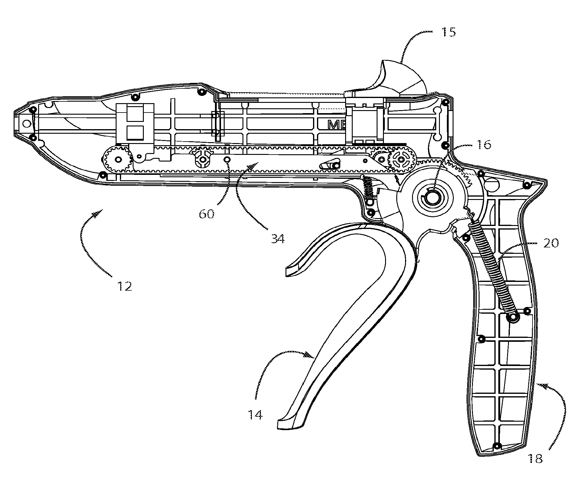
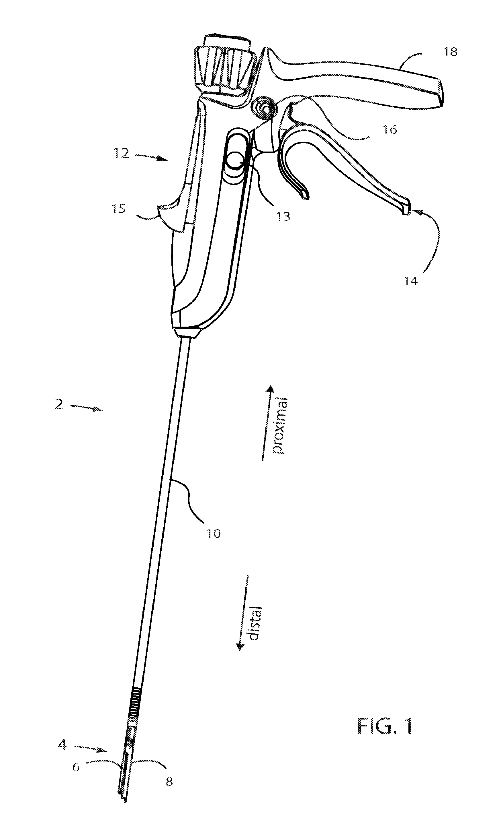
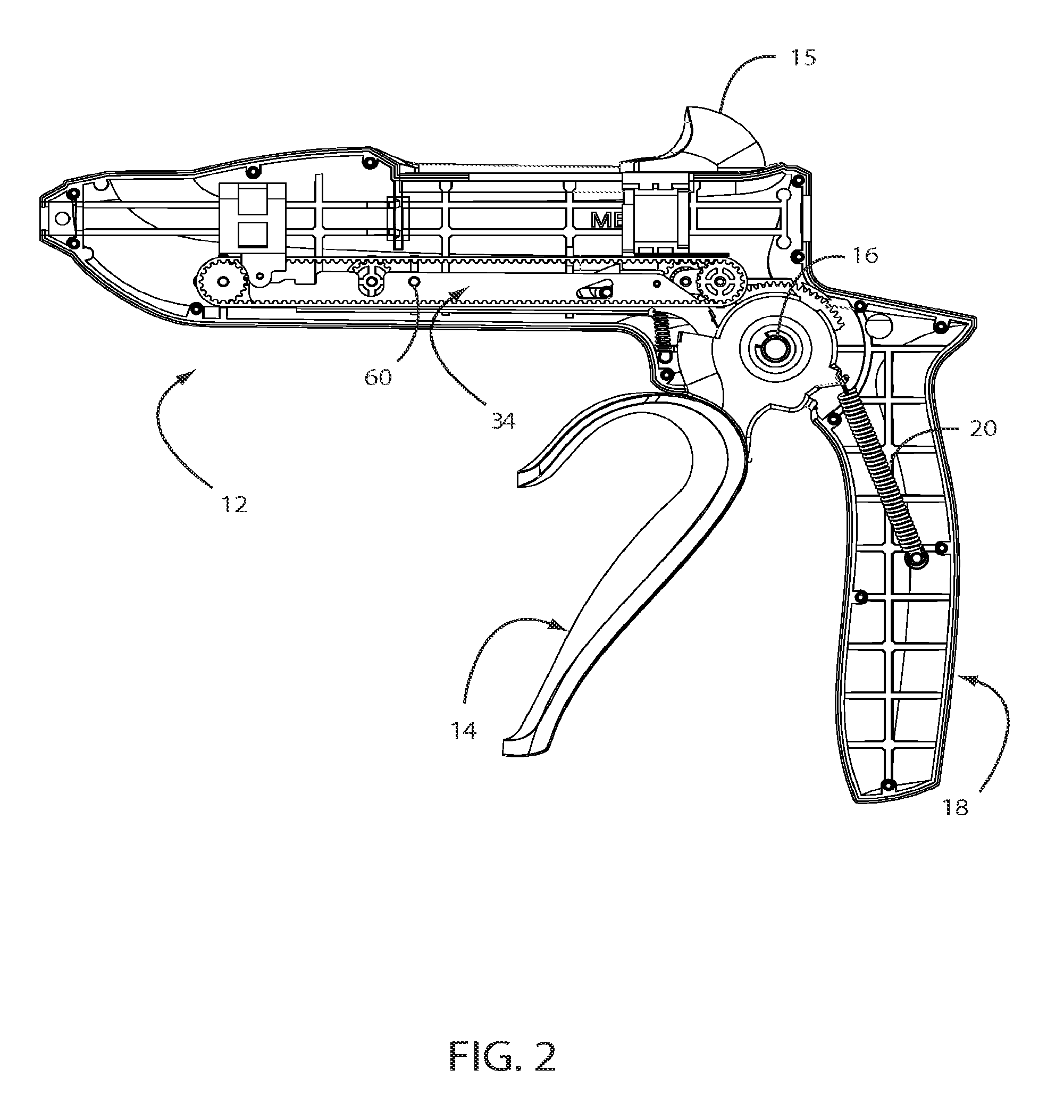
[0023]Referring to FIG. 1, an exemplary surgical stapler 2 may include an end effector 4, which in turn includes a staple holder 8 and an anvil 6, where at least one of the staple holder 8 and the anvil 6 are rotatable and / or otherwise movable relative to one another. Alternately, the staple holder 8 and the anvil 6 may be directly connected to one another in any other suitable manner, if desired. The staple holder 8 and anvil 6 may be configured substantially as set forth in the Endocutter Document. As another example, the staple holder 8 may be a single-use cartridge, detachable from a remainder of the end effector 4. If so, the feeder belt of the Endocutter Document may be fixed to the cartridge, or movable relative to the cartridge. As another example, where the staple holder 8 is a detacha...


PUM


Abstract

An exemplary surgical apparatus includes an end effector; and a handle operationally connected to the end effector, the handle including a trigger and a mode button; where the mode button is first in a neutral position in which actuation of the trigger causes the end effector to move to a clamped configuration; and where the mode button is movable laterally to a second position in which actuation of the trigger causes the end effector to deploy staples.

Description

FIELD OF THE INVENTION[0001]The invention generally relates to surgical instruments, and more specifically to the actuation of surgical instruments.BACKGROUND[0002]Minimally invasive surgery is performed through small incisions in the body, into which trocar ports may or may not be placed. One or more surgical instruments are inserted through each incision in order to perform the surgical procedure. In order to effectuate one of the objectives of minimally invasive surgery, which is the minimization of incisions to the body to reduce healing time and scarring, it is desirable to minimize the number of incisions made in the body. The number of incisions and their placement are determined by the particular surgical procedure to be performed and the configuration of the instruments used to carry out that procedure.[0003]One problem encountered during the performance of surgical stapling in a minimally-invasive procedure, or even an open surgical procedure, is the need for different tri...

Claims


Application Information

Patent Timeline
Patent Type & Authority Patents(United States)
IPC IPC(8): A61B17/068A61B17/072A61B17/00A61B17/29
CPCA61B17/07207A61B2017/2917A61B2017/2923A61B2017/00367
Inventor KNODEL, BRYAN D.LEV, YAEER E.
Owner AESCULAP AG
Learn More