Holding device for medical instruments

a technology for holding devices and medical instruments, applied in the direction of surgical instruments, shock absorbers, catheters, etc., can solve the problems of large weight, system volume, and the ability of known holding devices to be rarely disassembled

Active Publication Date: 2016-08-30
KARL STORZ GMBH & CO KG
View PDF29 Cites 268 Cited by
  • Summary
  • Abstract
  • Description
  • Claims
  • Application Information

AI Technical Summary

Benefits of technology

[0010]Because of the inventive configuration of the weight-relieving system as a resetting element acting on the bracket, it is possible to make the weight-relieving system as a compact, light construction so that the entire holding device can easily be disassembled and autoclaved for cleaning purposes.
[0013]Shape-memory alloys are distinguished in that they can resume their original shape after a relatively strong deformation. In conjunction with a shape-memory alloy this means that the material that has been extended in the area of its stress plateau without additional force being exerted resumes its original shape after the tractive stress has been discontinued.
[0015]To make possible a largely force-free actuation of the bracket, it is proposed according to the invention that the resetting element should be pre-stressed by the bracket load until reaching the plateau stress, so that the additional expansion of the resetting element falls directly into the force-free area of the stress plateau.
[0020]It is further proposed with the invention that the cable winch should be mounted on the displaceable bracket part by means of a flexible element, for example a link chain. The coupling of the cable winch with the displaceable bracket part by the link chain makes possible a uniform, non-jerking transmission of the forces exerted by the displaceable bracket part onto the cable winch that constitutes the weight-relieving system.

Problems solved by technology

With this known spring arrangement, it is possible to displace the holding device essentially free of weight, but this spring arrangement, like the constructions with counterweights as weight-relieving systems as known in the art, has the disadvantage that these systems take up considerable volume and in addition have great weight, and thus these known holding devices can rarely be disassembled after each use and autoclaved for cleaning purposes.

Method used


Image

  • Holding device for medical instruments
  • Holding device for medical instruments
  • Holding device for medical instruments

Examples


Embodiment Construction

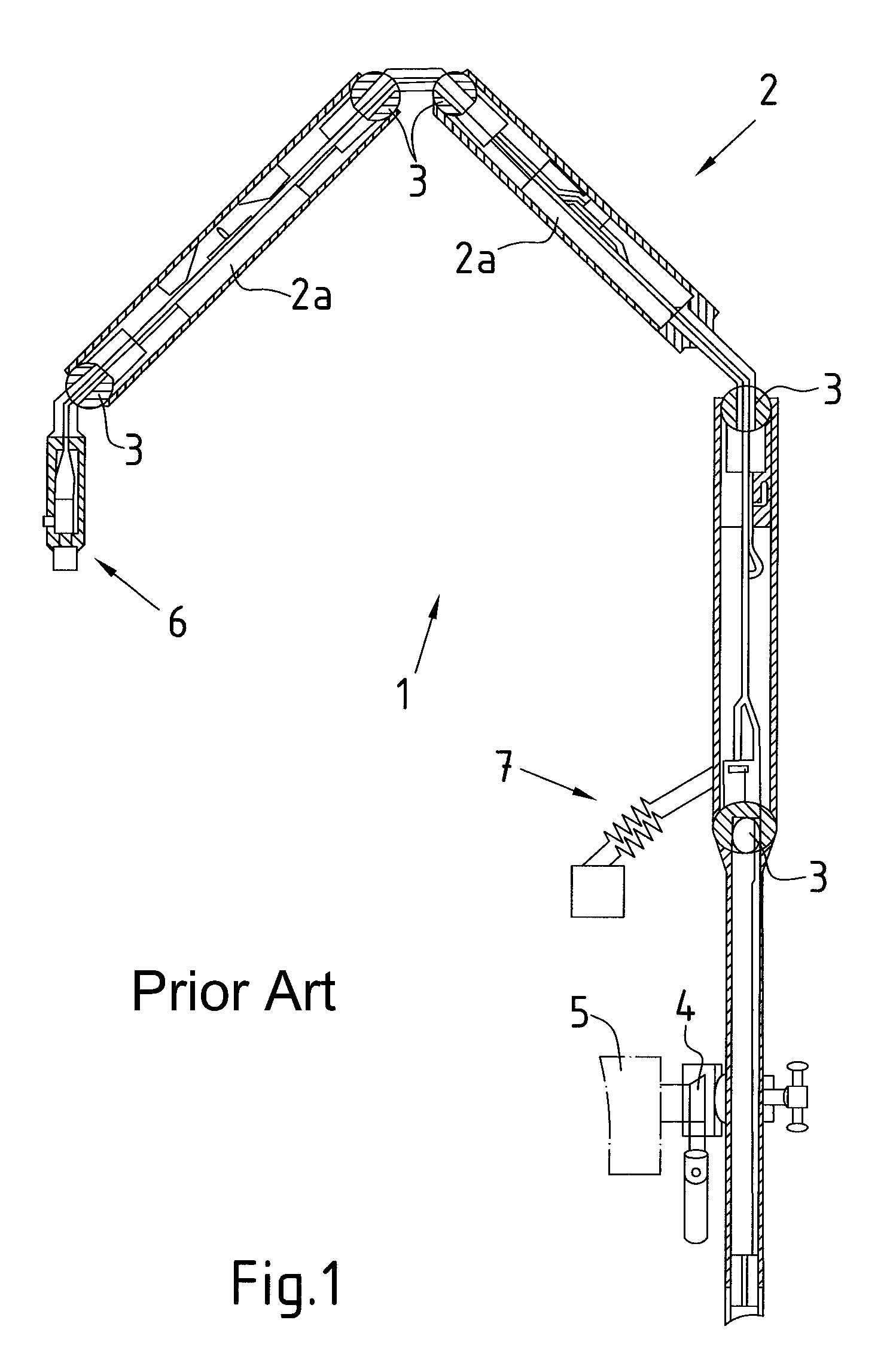
[0028]FIG. 1 shows a holding device 1 for medical instruments according to the state of the art.

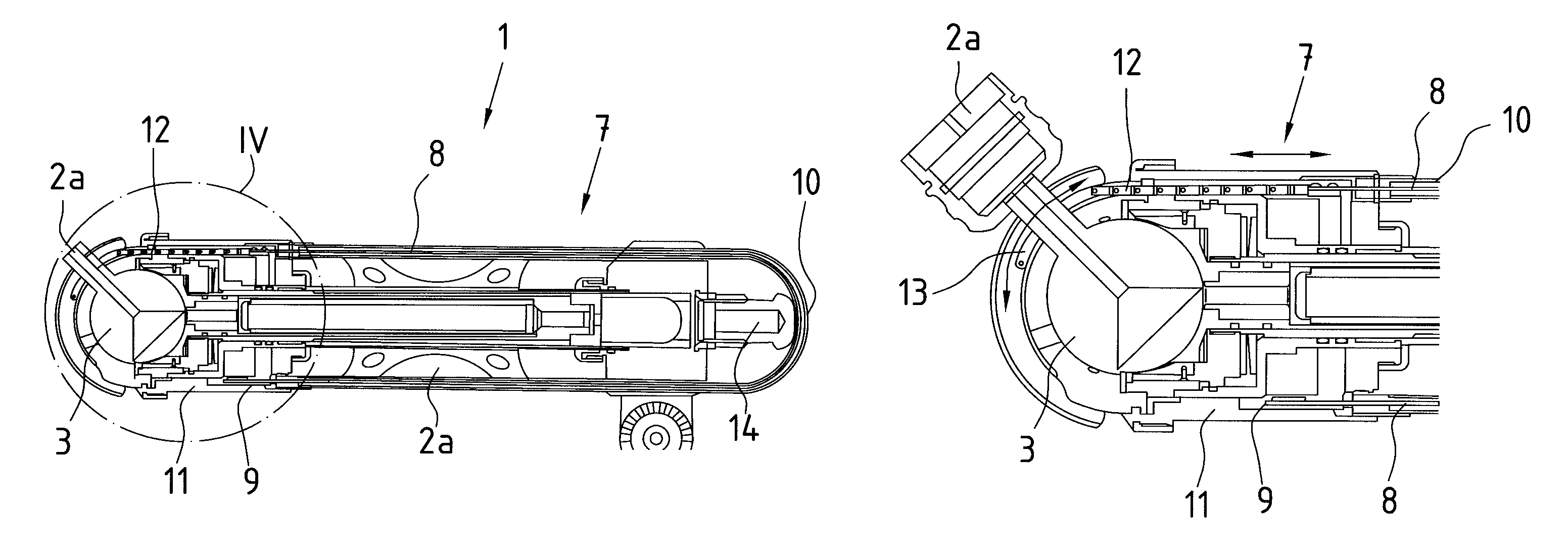
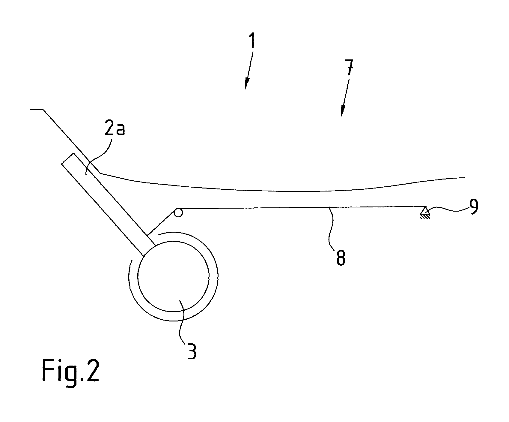
[0029]This holding device 1 consists essentially of a bracket 2 made up of several bracket parts 2a, such that the individual bracket parts 2a of the bracket are connected with one another so that they can rotate with respect to one another by a joint 3 configured as a ball and socket joint 3.

[0030]Holding devices 1 of this type are frequently required in executing surgical procedures in order to hold medical instruments of many types, such as retractors, microscopes, video cameras or endoscopes, in a certain position for an extended period. As a result of the jointed configuration of the holding device 1 it is possible for the surgeon to precisely position the medical instrument and to fix the selected position of the holding device 1 by blocking the joint 3 or joints 3. In addition to endoscopic surgery, such holding devices 1 find application in open or invasive surgery.

[0031]The brack...


PUM


Abstract

A holding device for medical instruments, having a bracket on which at least one medical instrument can be affixed, at least one joint to position the bracket and a weight-relieving system to compensate the bracket load. The holding device is of compact and light structure and for cleaning purposes is completely autoclavable together with the bracket. The weight-relieving system is configured as a resetting element that is coupled with the bracket and is made of a material that essentially includes a plateau stress.

Description

CROSS-REFERENCE TO RELATED APPLICATIONS[0001]The present application claims priority of German patent application No. 10 2009 060 495.2 filed on Dec. 23, 2009, the content of which is incorporated herein by reference.FIELD OF THE INVENTION[0002]The invention relates to a holding device for medical instruments, with a bracket on which at least one medical instrument can be affixed, with at least one joint to position the bracket and with a weight-relieving system to compensate the bracket load.BACKGROUND OF THE INVENTION[0003]Holding devices of this type are often required in executing surgical procedures, to hold medical instrument of the most varied types, such as retractors, video cameras or endoscopes, in a certain position for extended periods. As a result of the jointed configuration of the holding device, it is possible for the surgeon to precisely position the medical instrument held by the bracket and to stabilize the selected position of the holding device by blocking the j...

Claims


Application Information

Patent Timeline
Patent Type & Authority Patents(United States)
IPC IPC(8): A47F5/00A61B1/00F16F1/02E04G3/00A61B18/18F16M11/10F16M13/02A61M25/01A61B17/00
CPCA61B1/00149F16F1/021A61B90/50A61B2017/00867F16F2224/0258F16F2230/0011A61B2090/5025A61B2090/0813F16M11/10F16M13/02A61M25/0141F16M13/022A61M2205/0266
Inventor STEFAN, JOCHENBACHER, UWE
Owner KARL STORZ GMBH & CO KG
Why Eureka
Try Eureka