Laser projector

a laser projector and projector technology, applied in the field of laser projectors, can solve problems such as difficulty in realizing sharp clean images, and achieve the effect of enhancing the touch recognition ra

Active Publication Date: 2016-09-27
LG ELECTRONICS INC
View PDF14 Cites 4 Cited by
  • Summary
  • Abstract
  • Description
  • Claims
  • Application Information

AI Technical Summary

Benefits of technology

[0037]Still further, noise infrared lights may be removed, except the infrared lights reflected by the screen out of the infrared lights detected by the detector. Accordingly, a touch recognition rate may be enhanced.

Problems solved by technology

However, it is difficult to realize a sharp clean image because an image projected on a screen might be out of focus according to a position of the screen.

Method used


Image

  • Laser projector
  • Laser projector
  • Laser projector

Examples


first embodiment

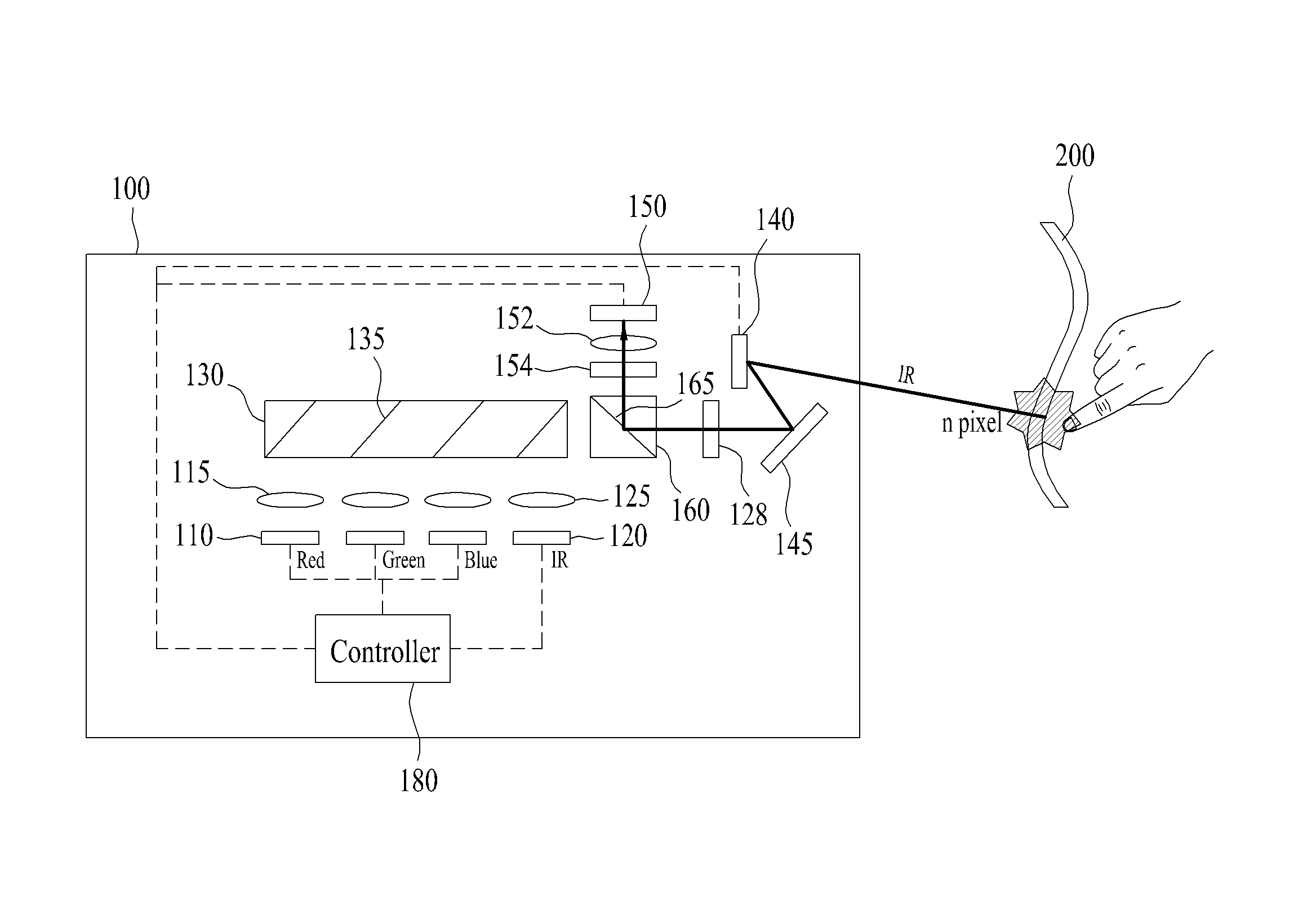
[0079]FIG. 6a is a conceptual diagram of a laser projector 100 according to the present invention. This embodiment has a characteristic that image emission, infrared light emission and infrared light detection are performed by the scanner 140.

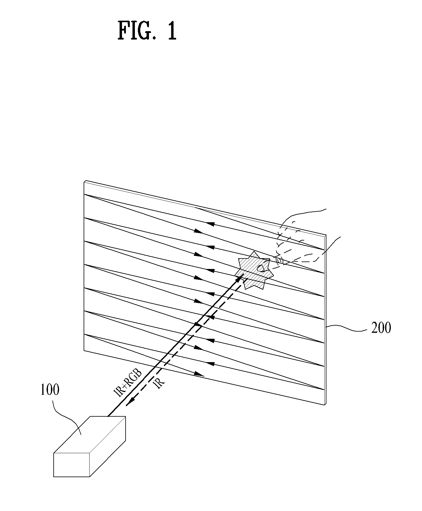
[0080]The screen 200 provided in the laser projector 100 according to the present invention projects an image to a back side of the screen 200. A user may see an image on the opposite side of the screen with respect to the side to which the image is projected and inputs touch, while seeing the screen. The screen 200 may be a three-dimensional model showing topography, a predetermined portion of a case provided in a home appliance and a wall of a building.

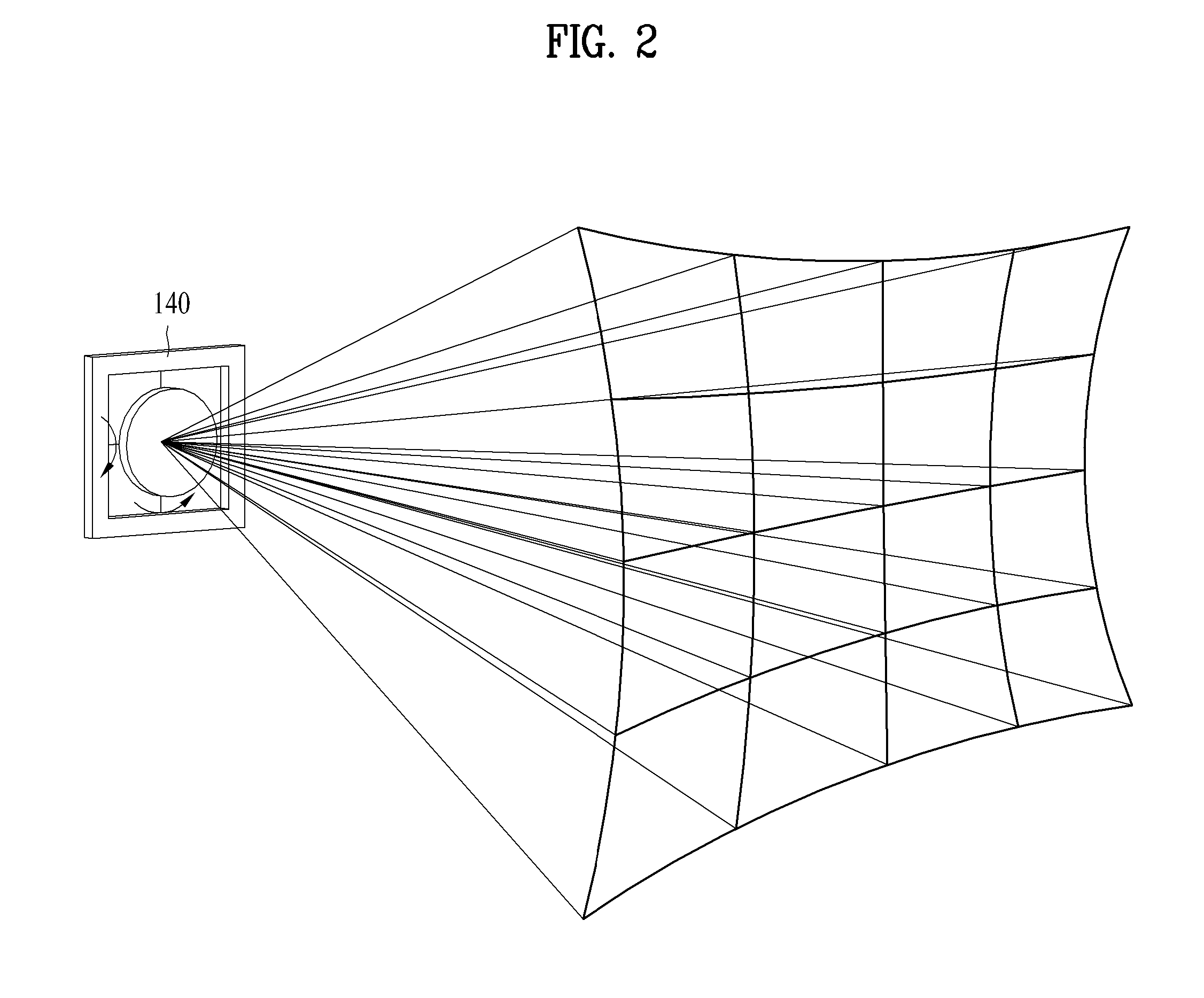
[0081]The scanner 140 is used and the screen 200 may be applied to a curved screen 200. A clean image is imaged on the screen, regardless of the distance between the scanner 140 and the screen 200, such that the screen 200 using the scanner 140 may realize an image even on a curved surface.

[008...

second embodiment

[0105]FIGS. 8a and 8b are conceptual diagrams of a laser projector 100 according to the present invention. In this embodiment, a polarization beam splitter may reflect only a visible light and a transmitted infrared light and include a polarization surface 165 configured to pass the received infrared light, which is different from the embodiment shown in FIGS. 6a and 6b.

[0106]FIG. 10 is a graph illustrating a characteristic of the polarization surface 165 used in this embodiment. The polarization surface 165 passes an S-wave in a longer wavelength than the wavelength of the infrared light and reflects a visible light and an infrared light. In other words, P-wave and S-wave in the visible light wavelength may be reflected. Only P-wave in the infrared light wavelength may pass or S-wave may be reflected.

[0107]In this embodiment, the light emitted from the light source 110 and the infrared light emitted from the infrared light emitting device 120 are S-wave infrared lights. As shown i...

fourth embodiment

[0113]FIG. 12 is a conceptual diagram of a laser projector according to the present invention. In this embodiment, a pin-hole 170 may be provided between the detector 150 and the lens 125. The pin-hole 170 passes only an infrared light drawn in a specific direction and shuts off the light incident after scattered by the infrared light emitting device 120. In other words, the scattered light is incident near the pin-hole 170 and fails to pass through the pin-hole 170 such that it cannot be detected by the detector 150.

[0114]The lens 125 may be provided in front of the pin-hole 170 for the light reflected by the screen 200 to pass through the pin-hole 170, such that the light may be incident to the pin-hole 170 after passing through the lens 125. In case a direction of the light incident on the lens 125 is different from a direction of the light reflected by the screen 200, the light may penetrate the lens 125 to be incident on a point near the pin-hole 170. Accordingly, noise of the ...


PUM


Abstract

There are disclosed a laser projector configured to project an image to a back side of a screen and to detect a touch input, comprising a light source configured to irradiate at least one of red, green and blue lights, an infrared light emitting device configured to emit an infrared light to the screen, a light synthesis system configured to synthesize image information comprising color information for each pixel with the light irradiated from the light source so as to emit the synthesized light, a scanner configured to project the synthesized light toward the screen for each pixel, a detector configured to detect an infrared light reflected by an object approaching the screen, and a controller configured to control operations of the light source, the infrared light emitting device and the scanner and to recognize touch input based on the information detected by the detector, such that the laser projector that may perform the projection of the image to the screen and the touch recognition simultaneously may be provided, only to be small-sized.

Description

[0001]Pursuant to 35 U.S.C. §119(a), this application claims the benefit of earlier filing date and right of priority to Korean Application No. 10-2013-0033353, filed on Mar. 28, 2013, the contents of which are hereby incorporated by reference herein in their entirety.BACKGROUND OF THE DISCLOSURE[0002]1. Field of the Disclosure[0003]The present invention relates to a laser projector that senses touch, while realizing an image by using a laser light source and a scanner.[0004]2. Discussion of the Related Art[0005]A projection type image display device (namely, a projector) can realize a large image, with no auxiliary display panel. Such a projection type display device is used in realizing a screen for a conference or meeting and is small-sized as an image display device for children.[0006]A conventional projection type display device (a conventional projector) typically uses a light emitting diode as a light source. Recently, a laser projector emerges that uses a laser as a light so...

Claims


Application Information

Patent Timeline
Patent Type & Authority Patents(United States)
IPC IPC(8): G03B21/14G03B21/20G06F3/041G06F3/042H04N9/31
CPCG03B21/142G03B21/2073G06F3/0416G06F3/0423H04N9/3129G06F3/0421G03B21/14G06F3/03G06F3/042
Inventor YOON, CHANYOUNGKWON, JAEWOOK
Owner LG ELECTRONICS INC
Why Eureka
Try Eureka