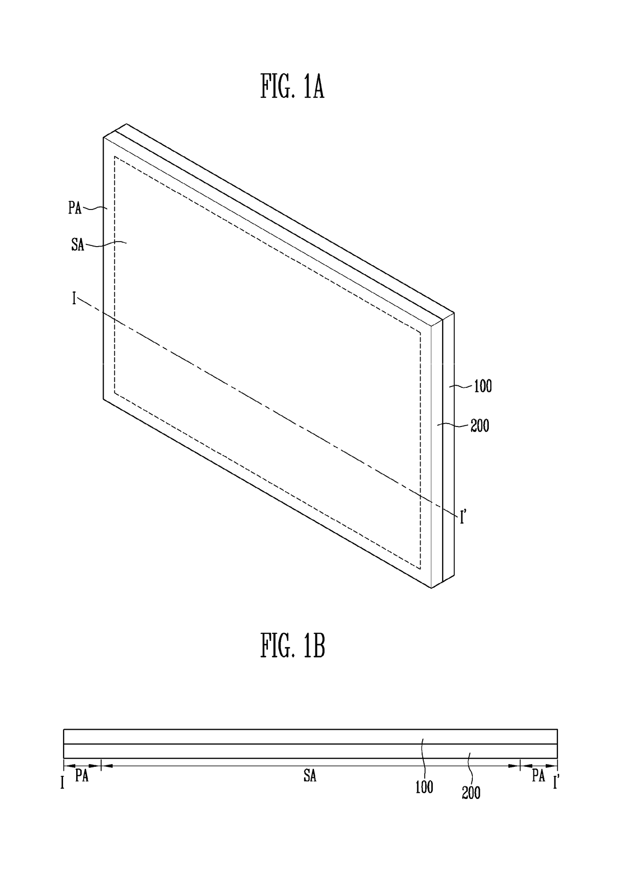
Touch panel and display device including the same

a display device and touch sensor technology, applied in the field of touch sensor and display device, can solve the problems of poor touch recognition rate and limited dimension constraints of touch sensor electrodes, and achieve the effects of improving the touch recognition rate of the touch panel, ensuring capacitance, and visual transparency

Active Publication Date: 2019-03-19
SAMSUNG DISPLAY CO LTD +1
View PDF4 Cites 0 Cited by
  • Summary
  • Abstract
  • Description
  • Claims
  • Application Information

AI Technical Summary

Benefits of technology

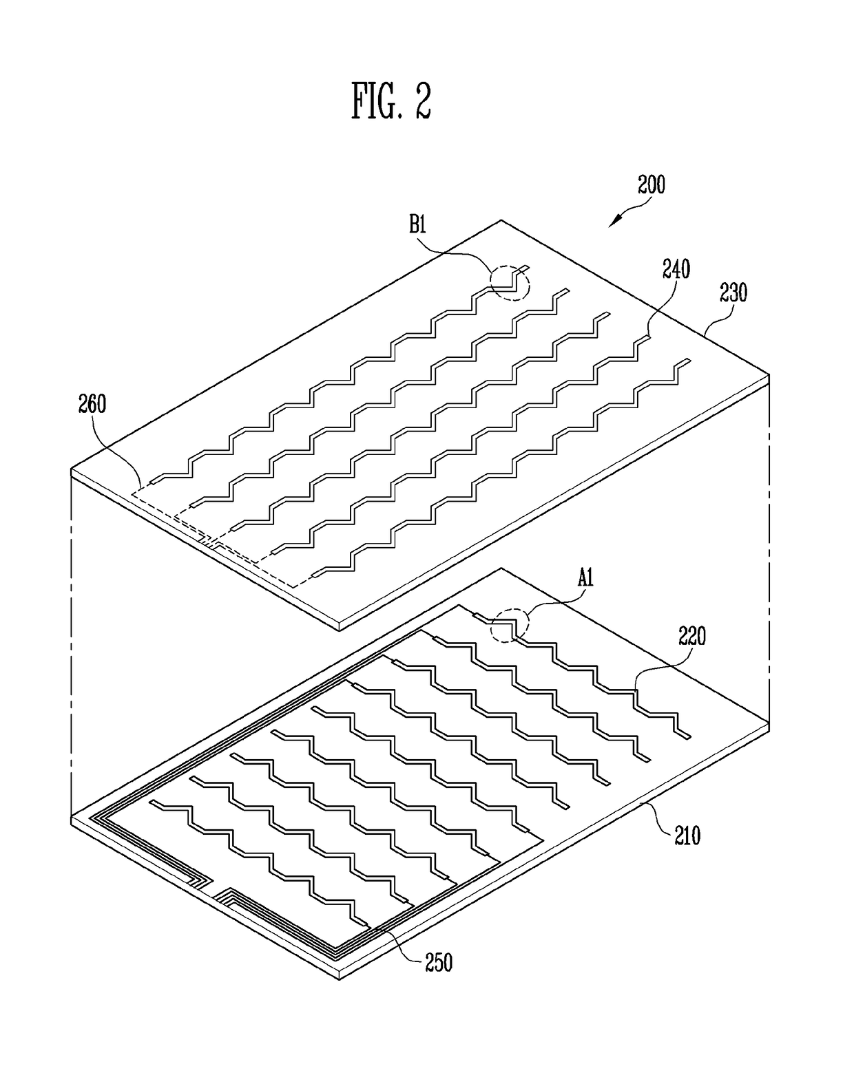
[0007]Exemplary embodiments provide a touch panel and a display device including the touch panel configured to ensure capacitance and to improve a touch recognition rate of the touch panel as well as be visually transparent to a user.
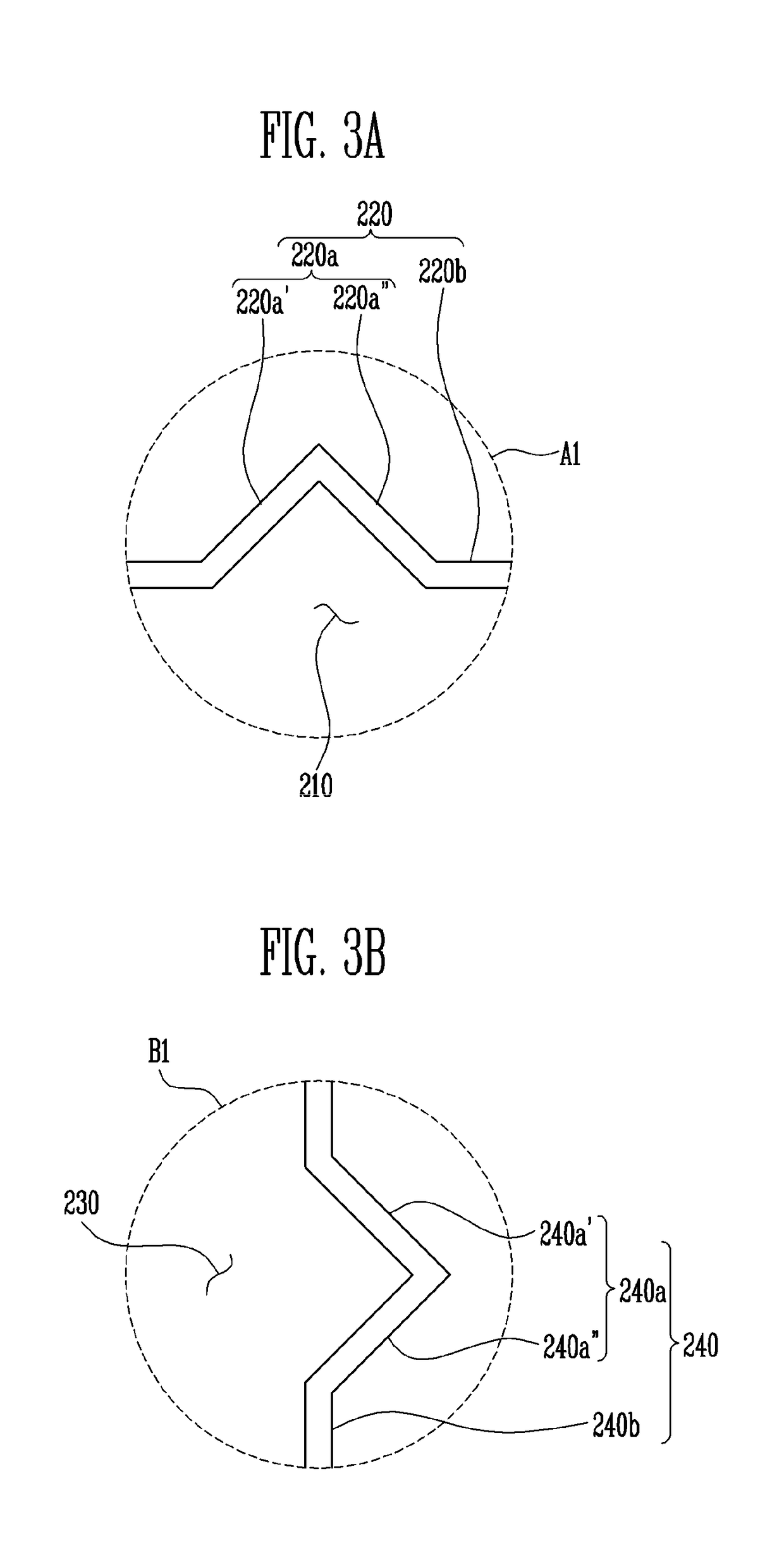
[0012]According to an exemplary embodiment, it is possible to improve a touch recognition rate of the touch panel by modifying the structure of the touch electrode of the touch panel and inducing a large change of capacitance.
[0013]Moreover, an aperture ratio of the display device may be improved by disposing the touch electrode to overlap with the emission area in the display device provided with the above-described touch panel.

Problems solved by technology

However, touch sensor electrodes typically have limited dimension constraints in order to avoid poor touch recognition rates due to resistivity and to visibility.

Method used


Image

  • Touch panel and display device including the same
  • Touch panel and display device including the same
  • Touch panel and display device including the same

Examples


Embodiment Construction

[0029]In the following description, for the purposes of explanation, numerous specific details are set forth in order to provide a thorough understanding of various exemplary embodiments. It is apparent, however, that various exemplary embodiments may be practiced without these specific details or with one or more equivalent arrangements. In other instances, well-known structures and devices are shown in block diagram form in order to avoid unnecessarily obscuring various exemplary embodiments.

[0030]In the accompanying figures, the size and relative sizes of layers, films, panels, regions, etc., may be exaggerated for clarity and descriptive purposes. Also, like reference numerals denote like elements.

[0031]When an element or layer is referred to as being “on,”“connected to,” or “coupled to” another element or layer, it may be directly on, connected to, or coupled to the other element or layer or intervening elements or layers may be present. When, however, an element or layer is re...


PUM


Abstract

A touch panel includes a first touch electrode disposed on a base substrate and a second touch electrode disposed on an insulating layer, which is disposed over the first touch electrode. The first touch electrode includes a first linear pattern disposed along a first direction and a first protrusion pattern extending from the first linear pattern. The second touch electrode includes a second linear pattern disposed along a second direction crossing the first direction and a second protrusion pattern extending from the second linear pattern. Wires connect the first touch electrode and the second touch electrode to a driving circuit. The second protrusion pattern partially overlaps the first protrusion pattern.

Description

CROSS-REFERENCE TO RELATED APPLICATION[0001]This application claims priority from and the benefit of Korean Patent Application No. 10-2016-0006067 filed on Jan. 18, 2016, which is hereby incorporated by reference for all purposes as if fully set forth herein.BACKGROUND[0002]Field[0003]Exemplary embodiments relate to a touch panel and a display device including the touch panel.[0004]Discussion of the Background[0005]Touch panels have seen explosive growth in recent years. Touch panels are sensing devices that are provided at a display side of display devices to be use as an input source to an attached or integrated computing device such as a smart phone, tablet, desktop computer, or laptop computer. Touch panels include touch sensor electrodes having a material with high electrical conductivity. However, touch sensor electrodes typically have limited dimension constraints in order to avoid poor touch recognition rates due to resistivity and to visibility.[0006]The above information d...

Claims


Application Information

Patent Timeline
Patent Type & Authority Patents(United States)
IPC IPC(8): G06F3/041G06F3/044
CPCG06F3/0418G06F3/0412G06F3/044G06F3/0445G06F3/04164G06F3/0446G06F3/0448
Inventor KWON, JUN ILBIEN, FRANKLINKIM, JAE JOONHEO, SANGHYUNMA, HYUNGGUNNA, KYUNGMIN
Owner SAMSUNG DISPLAY CO LTD
Why Eureka
Try Eureka