

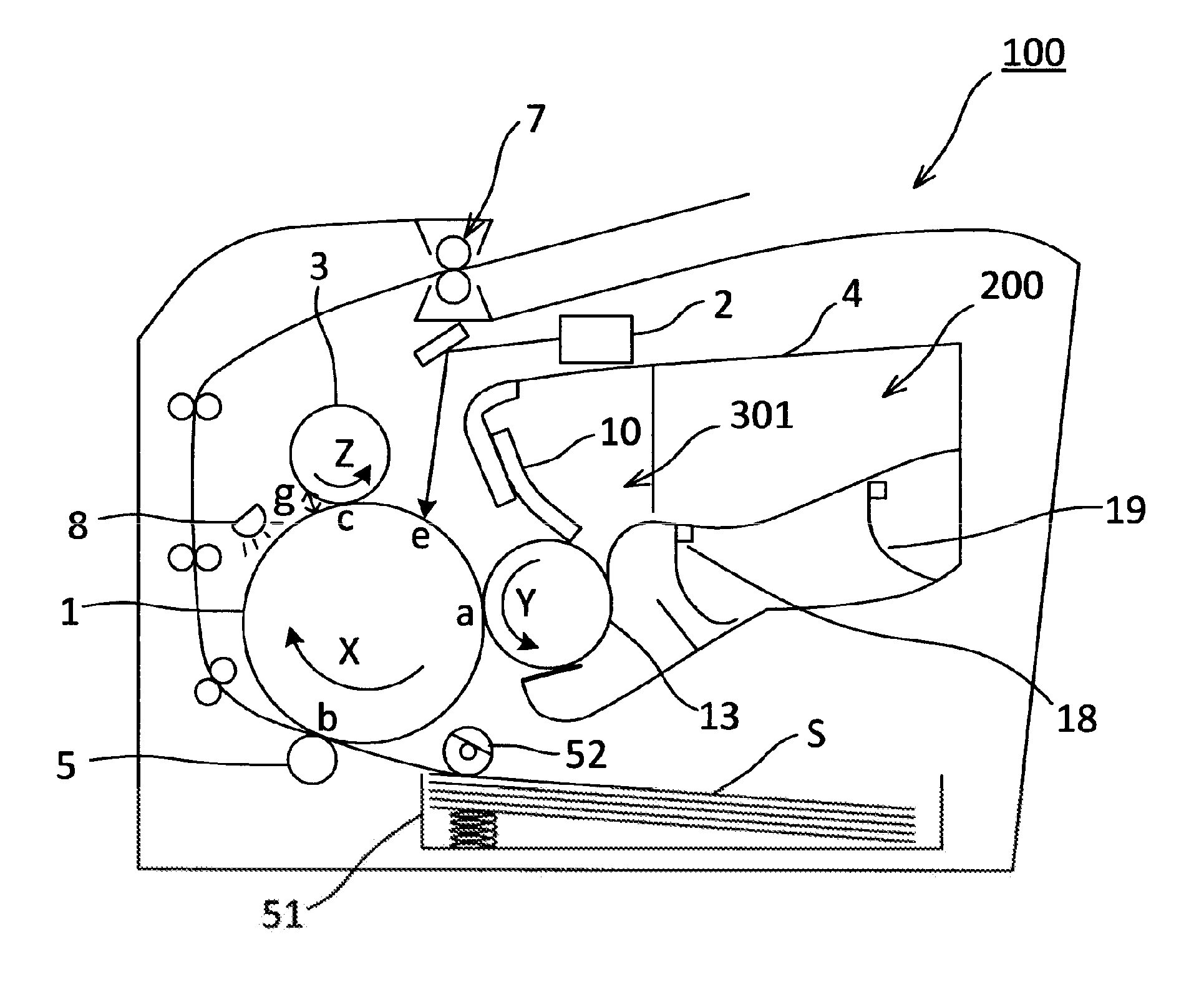
Image forming apparatus having simultaneous development and cleaning
a technology of image bearing and charging roller, which is applied in the direction of electrographic process apparatus, instruments, corona discharge, etc., can solve the problems of inability to retain an adequate charge, inability to uniformly charge the photosensitive drum, and particularly frequent post-black fogging, etc., to achieve the effect of reducing the number of times the image bearing member is charged
- Summary
- Abstract
- Description
- Claims
- Application Information
AI Technical Summary
Benefits of technology
Problems solved by technology
Method used
Image

Examples
example 1
[0063]The following provides an explanation of Example 1. In the configuration of Example 1, uneven charging caused by post-black fogging toner adhered to the charging roller 3 can be inhibited. In Example 1, developing roller pitch and charging roller pitch were made to be equal. Namely, Hc / Rc=Hd / Rd. More specifically, in Example 1, the outer diameter Hd of the developing roller 13 was made to be 12 mm and the circumferential velocity ratio Rd of the developing roller 13 to the photosensitive drum 1 was made to be 120%. In addition, the outer diameter Hc of the charging roller 3 was made to be 9 mm and the circumferential velocity ratio Rc of the charging roller 3 to the photosensitive drum 1 was made to be 90%.
[0064]In Example 1, a first round of post-black fogging occurs and that post-black fogging toner reaches the charging zone c due to rotation of the photosensitive drum 1. At that time, a portion of the post-black fogging toner that was not imparted with an adequate charge by...
example 2
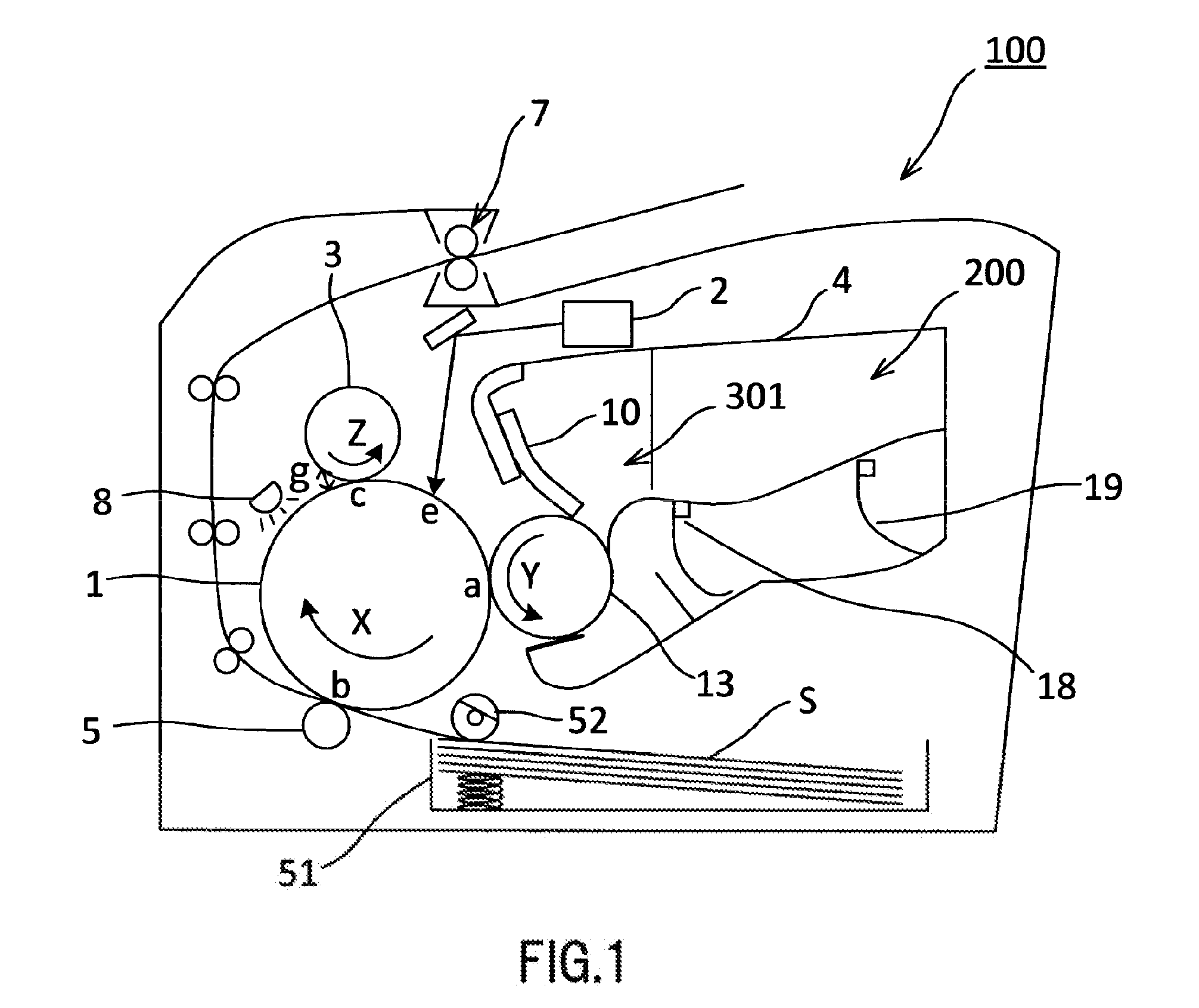
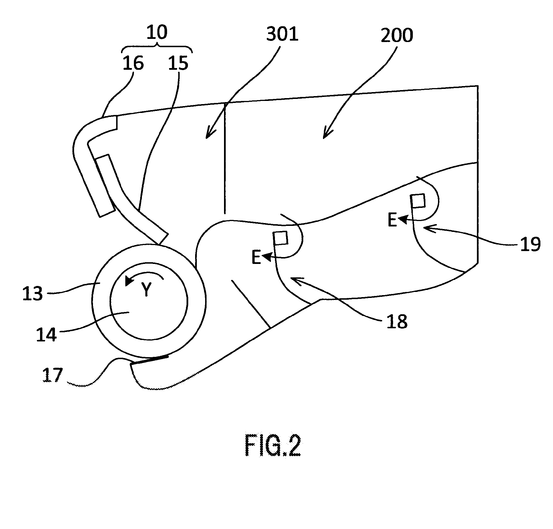
[0067]Next, an explanation is provided of Example 2. In Example 2, the charging roller pitch is made to be longer than the developing roller pitch. Namely, Hc / Rc>Hd / Rd. More specifically, in Example 2, the outer diameter Hd of the developing roller 13 is 12 mm and the circumferential velocity ratio Rd of the developing roller 13 to the photosensitive drum 1 is 140%. In addition, the outer diameter Hc of the charging roller 3 is 9 mm and the circumferential velocity ratio Rc of the charging roller 3 to the photosensitive drum 1 is 90%.
[0068]In the case of a long charging roller pitch, even in the case in which post-black fogging toner has been generated for one rotation of the developing roller 13, toner is not adhered over the entire circumference of the charging roller 3. Namely, the trailing end of the post-black fogging toner is on the charging roller 3 when the leading end of post-black charging toner adhered to the charging roller 3 has again reached the charging zone c. Conseq...
PUM
 Abstract
Description
Claims
Application Information