
Driver device, driving method for same, and display device

a technology of driver and display panel, which is applied in the direction of static indicating devices, instruments, etc., can solve the problems of affecting the display uniformity of the liquid crystal panel, the requirement of a manufacturing environment and a manufacturing difficulty are relatively high, and the charging efficiency of pixel storage capacitors and liquid crystal capacitors decreases, so as to achieve the effect of improving the display uniformity of the display panel

Inactive Publication Date: 2019-09-26
HKC CORP LTD +1
View PDF2 Cites 2 Cited by
  • Summary
  • Abstract
  • Description
  • Claims
  • Application Information

AI Technical Summary

Benefits of technology

The patent aims to improve the display uniformity of a liquid crystal panel by adjusting the duty cycle of an enable signal. It addresses the issue of uneven charging of pixel storage capacitors and liquid crystal capacitors caused by differences in impedance. The invention does not significantly change the existing production process and meets the requirements for process and cost. The technical effects include improved display uniformity and reduced visual differences across the panel.

Problems solved by technology

As the gate voltage decreases, the charging efficiency of a pixel storage capacitor and a liquid crystal capacitor decreases, finally affecting the display uniformity of the liquid crystal panel.
However, for the copper process, requirements on a manufacturing environment and a manufacturing difficultly are relatively high, and it is difficult to reduce costs.
It is difficult to satisfy a requirement on design of a panel having a narrow bezel when the area of the WOA is increased.

Method used


Image

  • Driver device, driving method for same, and display device
  • Driver device, driving method for same, and display device
  • Driver device, driving method for same, and display device

Examples


Embodiment Construction

[0034]The following embodiments are described with reference to the accompanying drawings, used to exemplify specific embodiments for implementation of this application.

[0035]Terms about directions mentioned in this application, such as “on”, “below”, “front”, “back”, “left”, “right”, “in”, “out”, and “side surface” merely refer to directions in the accompanying drawings. Therefore, the used terms about directions are used to describe and understand this application, and are not intended to limit this application.

[0036]The accompanying drawings and the description are considered to be essentially exemplary, rather than limitative. In the figures, modules with similar structures are represented by using the same reference number. In addition, for understanding and ease of description, the size and the thickness of each component shown in the accompanying drawings are arbitrarily shown, but this application is not limited thereto.

[0037]In the accompanying drawings, for clarity, thickn...


PUM


Abstract

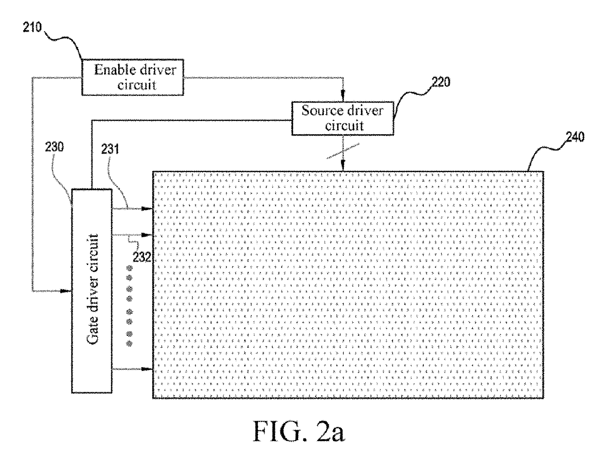
This application provides a driver device, a driving method for same, and a display device. The driver device includes: a gate driver circuit, connected to a plurality of gate lines, wherein the gate driver circuit inputs a gate driving signal to one of the plurality of gate lines according to an order; and an enable driver circuit, providing enable signals having different time lengths to the gate driver circuit within different scanning periods, to control input time points and time lengths for inputting the gate driving signal by the gate driver circuit to the gate line.

Description

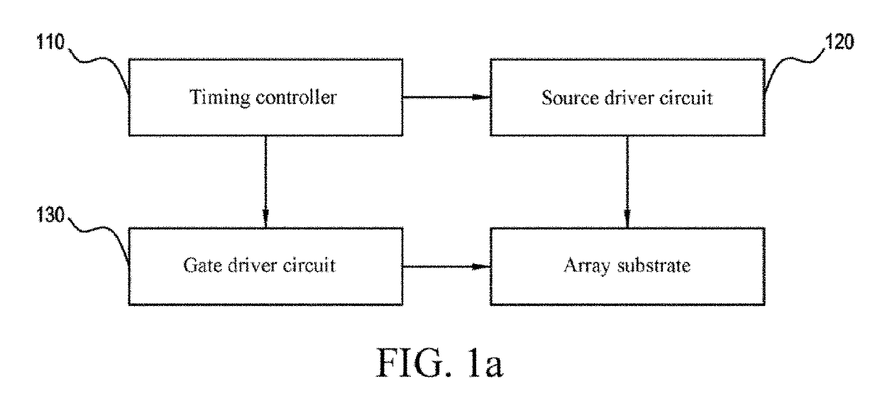
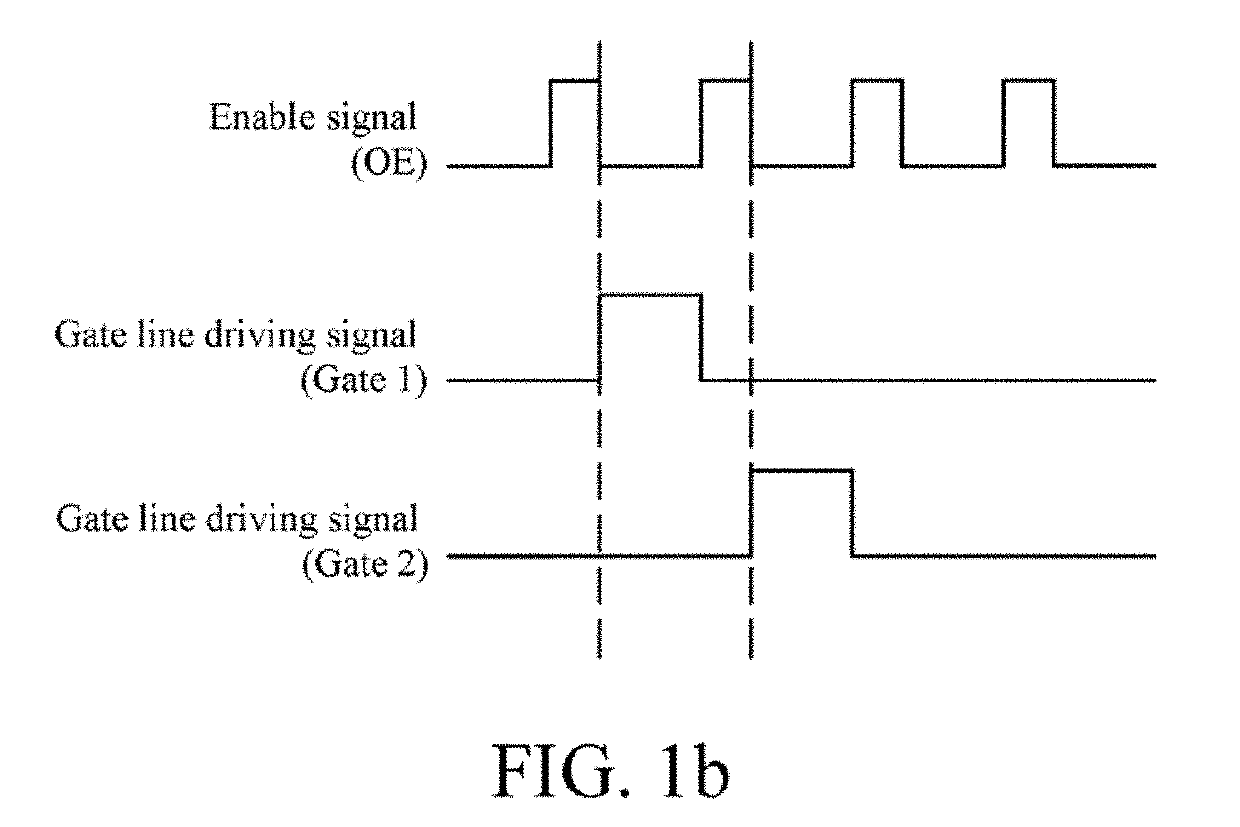
BACKGROUNDTechnical Field[0001]This application relates to the field of display technologies, and in particular, to a driver device, a driving method for same, and a display device.Related Art[0002]Currently, signal wires required by a gate driver circuit of a liquid crystal display panel are all wired on an array layer of the liquid crystal panel. Wires on the array layer are relatively thin, so that a corresponding impedance is relatively large.[0003]Moreover, for a gate side of the gate driver circuit, that is, a side where gate integrated circuits (Gate ICs) are disposed, a corresponding impedance increases when a wire on array (WOA) is longer. In addition, considering the resistance voltage division principle, a gate voltage (VGH) of the last gate integrated circuit of the gate driver circuit is far less than a gate voltage of the first gate integrated circuit connected to a source driver circuit. As the gate voltage decreases, the charging efficiency of a pixel storage capacit...

Claims


Application Information

Patent Timeline
Patent Type & Authority Applications(United States)
IPC IPC(8): G09G3/36
CPCG09G3/3688G09G2320/0233G09G2310/08G09G3/3696G09G3/3677G09G3/3648G09G3/3666
Inventor GUO, DONGSHENG
Owner HKC CORP LTD
Learn More