
Charging member, process cartridge, and electrophotographic image forming apparatus

a technology of electrophotographic image and process cartridge, which is applied in the direction of electrographic process, corona discharge, instruments, etc., can solve the problem of uneven charging to the surface of photosensitive members, and achieve the effect of removing the uneven charging of photosensitive members

Inactive Publication Date: 2014-08-07
CANON KK
View PDF8 Cites 5 Cited by
  • Summary
  • Abstract
  • Description
  • Claims
  • Application Information

AI Technical Summary

Benefits of technology

The present invention aims to provide a charging member that can prevent charging unevenness on a photosensitive member caused by vibration. This invention also aims to provide a process cartridge and an electrophotographic apparatus that can stably form high-quality electrophotographic images.

Problems solved by technology

In a contact charging method, vibration of the photosensitive member in an electrophotographic apparatus may cause unstable contact between the charging member and the photosensitive member, resulting in uneven charging to the surface of a photosensitive member in some cases.

Method used


Image

  • Charging member, process cartridge, and electrophotographic image forming apparatus
  • Charging member, process cartridge, and electrophotographic image forming apparatus
  • Charging member, process cartridge, and electrophotographic image forming apparatus

Examples


examples

[0124]The following specific examples further illustrate the present invention in details, but the scope of the present invention is not limited thereto.

Manufacturing Example A

Manufacturing of Fine Particles 1 (Conductive Fine Particles))

[0125]To 7.0 kg of silica particles (volume average particle diameter: 12.5 nm; volume resistivity: 1.8×10¹² Ω·cm), 140 g of methyl hydrogen polysiloxane was added with an edge runner operating, so that mixing / stirring was performed for 30 minutes with a line load of 588 N / cm (60 kg / cm). On this occasion, the stirring rate was 22 rpm. Carbon black particles (volume average particle diameter: 28 nm; volume resistivity: 1.2×10² Ω·cm) with an amount of 7.0 kg was added thereto for a time period of 10 minutes with an edge runner operating, and mixing / stirring was further performed for 60 minutes with a line load of 588 N / cm (60 kg / cm). As described above, the carbon black was attached to the surface of silica particles coated with methyl hydrogen polysi...

manufacturing example b

Manufacturing of Fine Particles 2 (Metal Oxide Fine Particles))

[0127]Needle-shaped rutile type titanium oxide particles (volume average particle diameter: 15 nm; aspect ratio (vertical:horizontal)=3:1; volume resistivity: 2.3×10¹⁰ Ω·cm) in an amount of 1,000 g was blended with 110 g of isobutyl trimethoxysilane as finishing agent and 3,000 g of toluene as solvent so as to prepare a slurry. The slurry was agitated with a stirrer for 30 minutes and then supplied to a visco mill filled with glass beads (trade name: “GB200M”, made by Potters-Ballotini Co., Ltd.) up to 80% of the effective capacity for wet crushing at a temperature of 35±5° C. Toluene was removed from the slurry produced by the wet crushing by distillation under reduced pressure (bath temperature: 110° C.; product temperature: 30 to 60° C.; pressure reduction degree: approximately 100 Torr (approximately 13.3 kPa)) with a kneader, and the finishing agent was baked at 120° C. for 2 hours. The baked particles were cooled d...

example 1

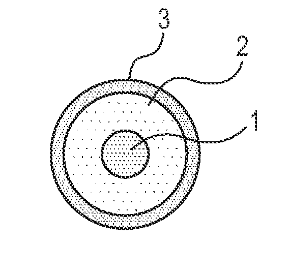
Manufacturing of Charging Roller 1

[0128]To a stainless steel rod having a diameter of 6 mm and a length of 252 mm was coated with a thermosetting adhesive (trade name: METALOC U-20, made by Toyokagaku Kenkyusho Co., Ltd.), which was then left standing in a hot-air oven at 200° C. for 30 minutes. An electro-conductive support was thus obtained.

[0129]In manufacturing a compound for the elastic layer, the materials shown in the following Table 1 were kneaded for 15 minutes with a closed type mixer which is adjusted at 50° C. for preparation of a rubber compound A.

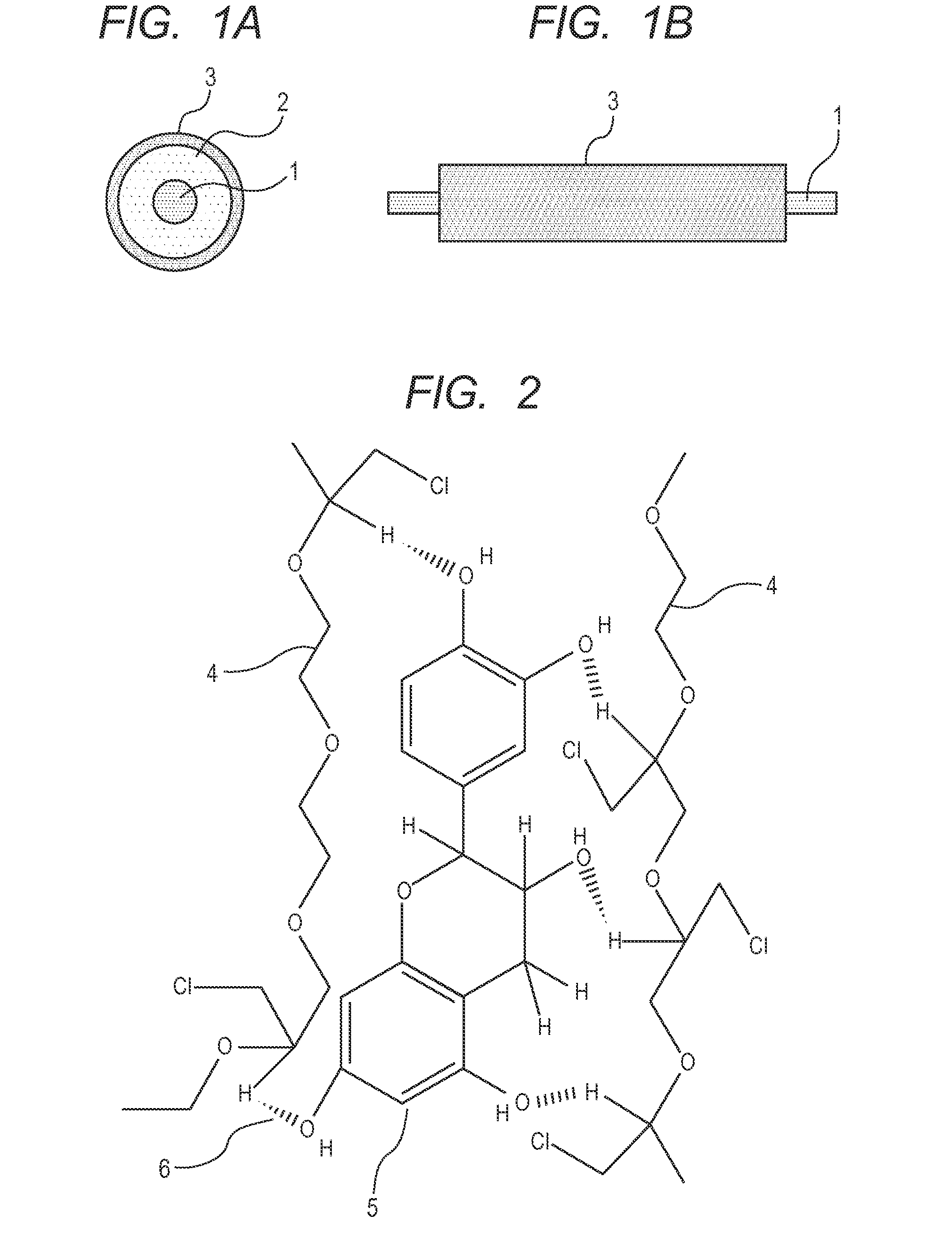
TABLE 1Parts byMaterial for rubber compound AmassEpichlorohydrin-ethylene oxide-allyl glycidyl ether copolymer100(EP:EO:AGE = 37:55:7.5)Tetrabutyl ammonium perchlorate3Epicatechin (compound represented by formula (5))15Zinc stearate1(trade name: SZ-2000, made by Sakai Chemical Industry Co.,Ltd.)Zinc oxide5(trade name: FLOWERS OF ZINC, 2 grade, made by SakaiChemical Industry Co., Ltd.)Calcium carbonate50(trade name: NANOX #30, ...


PUM

PropertyMeasurementUnit
volume resistivityaaaaaaaaaa

Abstract

In order to maintain the image quality of a recent high-speed electrophotographic apparatus, a charging member is provided which hardly causes charging unevenness of a photosensitive member even when vibration of the photosensitive member occurs. The charging member includes an electro-conductive support, an electro-conductive elastic layer, and a surface layer. The elastic layer contains a resin having an epichlorohydrin chain in the molecular structure and a specific flavonoid compound having two or more hydroxyl groups in the molecular structure.

Description

CROSS-REFERENCE TO RELATED APPLICATIONS[0001]This application is a continuation of International Application No. PCT / JP2013 / 007550, filed Dec. 24, 2013, which claims the benefit of Japanese Patent Application No. 2012-285241, filed Dec. 27, 2012.BACKGROUND OF THE INVENTION[0002]1. Field of the Invention[0003]The present invention relates to a charging member, a process cartridge, and an electrophotographic image forming apparatus.[0004]2. Description of the Related Art[0005]An electrophotographic image forming apparatus (hereinafter also referred to as electrophotographic apparatus) using an electrophotographic method mainly includes an electrophotographic photosensitive member (hereinafter also referred to as “photosensitive member”), a charging device, an exposure device, a developing device, a transferring device, and a fixing device. The charging device allows the surface of a photosensitive member to be charged to a predetermined potential through application of a voltage. A me...

Claims


Application Information

Patent Timeline
Patent Type & Authority Applications(United States)
IPC IPC(8): B05C1/08B32B27/00G03G15/02
CPCG03G21/18G03G15/02G03G15/0233Y10T428/2947C08K5/132C08K5/053
Inventor MIYAGAWA, NOBORUMATSUDA, HIDEKAZU
Owner CANON KK
Learn More