Capacitor switch with internal retracting impedance contactor

a technology of impedance contactor and capacitor switch, which is applied in the direction of air break switch, high-tension/heavy-dress switch, electrical apparatus, etc., can solve the problems of rotary contactor acceleration device that is cumbersome, requires a much larger container, and can not be used in a large container, so as to achieve less expensive, less complex, and less expensive

Active Publication Date: 2006-07-18
SOUTHERN STATES
View PDF19 Cites 15 Cited by
  • Summary
  • Abstract
  • Description
  • Claims
  • Application Information

AI Technical Summary

Benefits of technology

[0010]The configuration of the capacitor switch gives it a number of advantages over conventional capacitor switches, which are generally more expensive, more complex, and less reliable than the present design. In particular, the present capacitor switch typically includes a ring shaped impedance contactor positioned around a probe-and-socket type penetrating main power contactor, which allows both contactors to operate in a linearly travel path. This allows both contactors to be housed within a relatively slender insulator forming the container filled with dielectric gas, which is smaller and less expensive than the containers of conventional circuit breakers and capacitor switches. In addition, the charging impedance is preferably located within a conductive cap on the outside and at the end of the insulator, which allows the charging impedance to be easily removed and replaced without opening the insulator or otherwise disassembling the switch. This design feature also removes the charging impedance from the temperature sensitive insulator and its temperature sensitive internal components, such as seals and the dielectric gas in the area of the main power contactor. Moreover, physically separating the insulator from the conductive cap, which is energized along with the impedance as part of the capacitor terminal, allows the insulator to be replaced by an electrically grounded conductive container for use in a “dead tank” configuration.
[0011]In addition, the timing device of the present capacitor switch is typically configured as a puffer mechanism within a retracting, but otherwise fixed, contact of the impedance contactor. This avoids locating the timing mechanism on the moving contact of the impedance contactor, which would increase the weight of the moving portion of the switch that has to be accelerated to a sufficient separation speed on the opening stroke to avoid a restrike. This design technique, in turn, is reflected in a smaller and less expensive accelerator mechanism for the switch. In addition, the charging impedance is electrically connected to the contactor with properly insulated internal posts, which avoids external components and linkages that would add cost and complexity to the switch.
[0013]For example, this container may include a grounded conductive tank in what is generally referred to as a “dead tank” configuration. Alternatively, the container may include an insulator extending between first and second ends a sufficient distance to prevent arcing from occurring between a first electric power terminal located at the first end and a second electric power terminal located at the second end when a rated voltage for the switch is applied across the power terminals. In addition, the impedance may be housed within a conductive cap forming a part of the first electric power terminal located at the first end of the insulator. To avoid the use of linkages and external components, the charging impedance may be electrically connected to the contactors within the insulator with internal posts. With this configuration, the present switch may be used to introduce a capacitor into the electric power circuit during the closing stroke, and to disconnect the capacitor from the electric power circuit during the opening stroke. To avoid system disturbances when switching the capacitor out of the circuit, the switch may also include an accelerator driving the power contactor and the impedance contactor at sufficient speed to avoid a restrike during the opening stroke.

Problems solved by technology

The basic design challenge for this type of device involves engineering an acceleration mechanism that obtains the desired contractor velocity quickly enough to extinguish the arc without experiencing an undesired restrike.
The resulting current transient also causes a transient surge in the voltage of the electric power system.
However, this device requires a large container to house the charging impedances.
In addition, the switching device described in this patent includes a rotary contactor acceleration device that is cumbersome and requires a much larger container than a linear moving contactor arrangement.
Therefore, this design is appropriate for a high voltage circuit breaker, but it is an expensive and relatively unreliable alternative for use as a capacitor switch that is intended to operate daily or several times a day.
As a result, the whip can become frozen in place during freezing rain or sleet condition, which can disable the whip portion of the device and thereby decrease its reliability.
In addition, the external moving components of the whip configuration increase the cost and complexity of the device, and can impose a significant additional maintenance requirement for the capacitor switch, which is intended to operate daily or several times a day for most application.

Method used


Image

  • Capacitor switch with internal retracting impedance contactor
  • Capacitor switch with internal retracting impedance contactor
  • Capacitor switch with internal retracting impedance contactor

Examples


Embodiment Construction

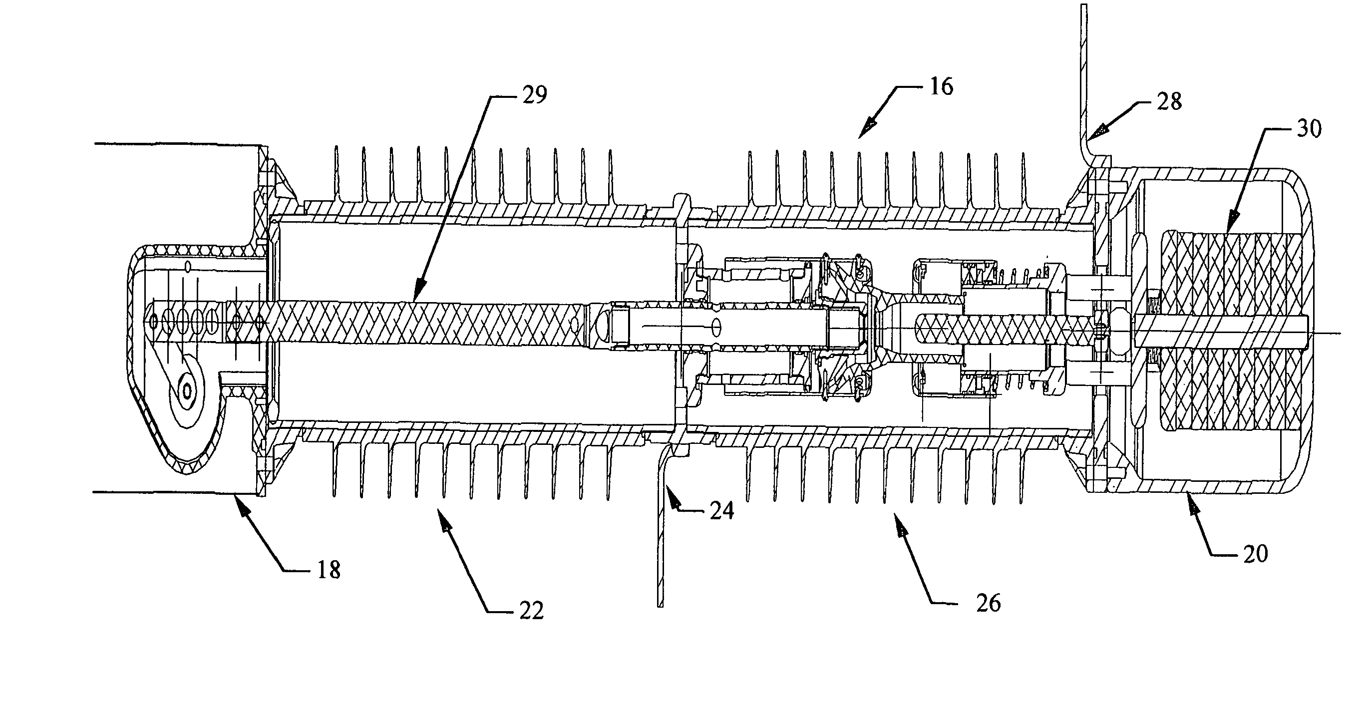
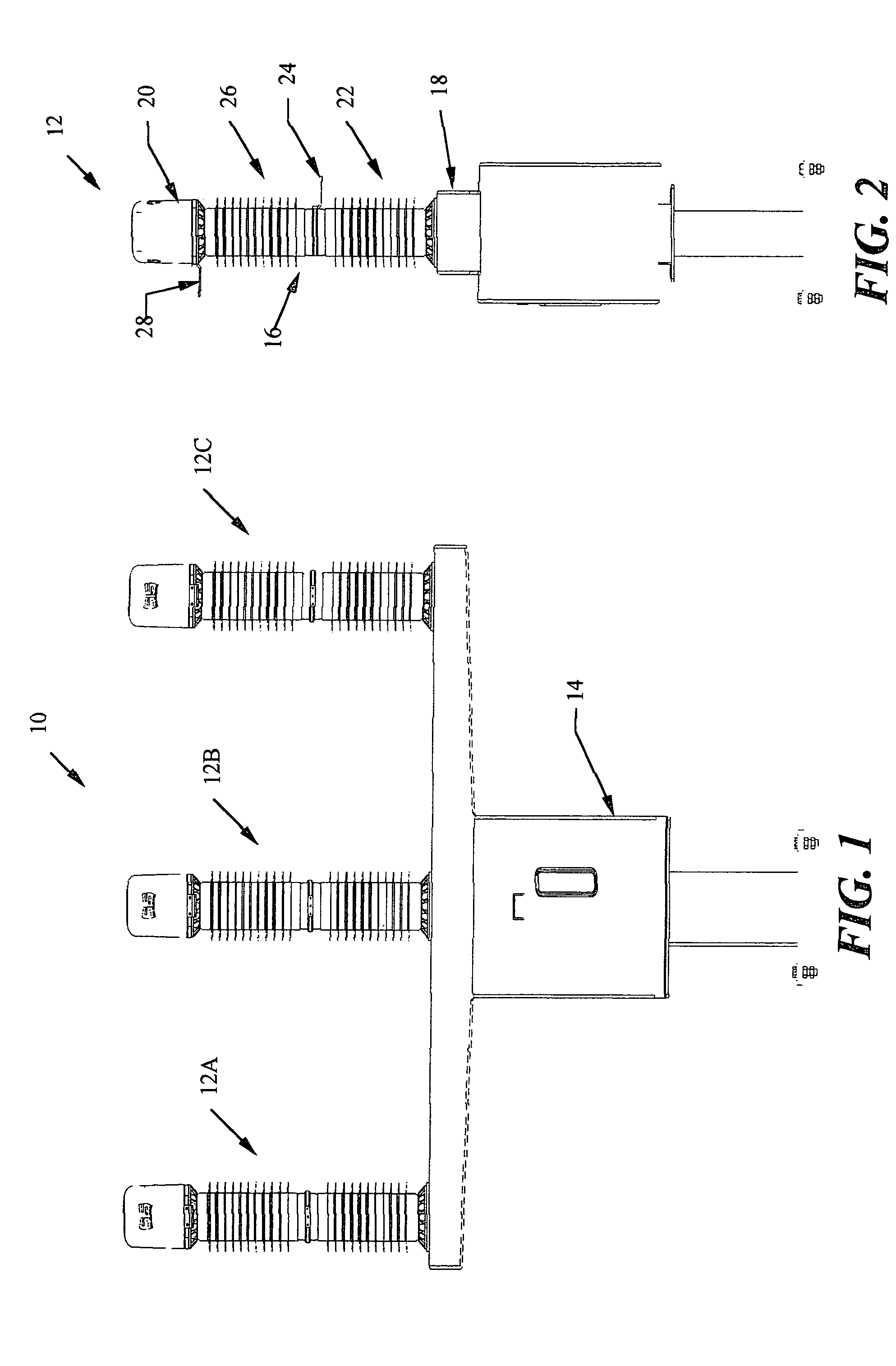
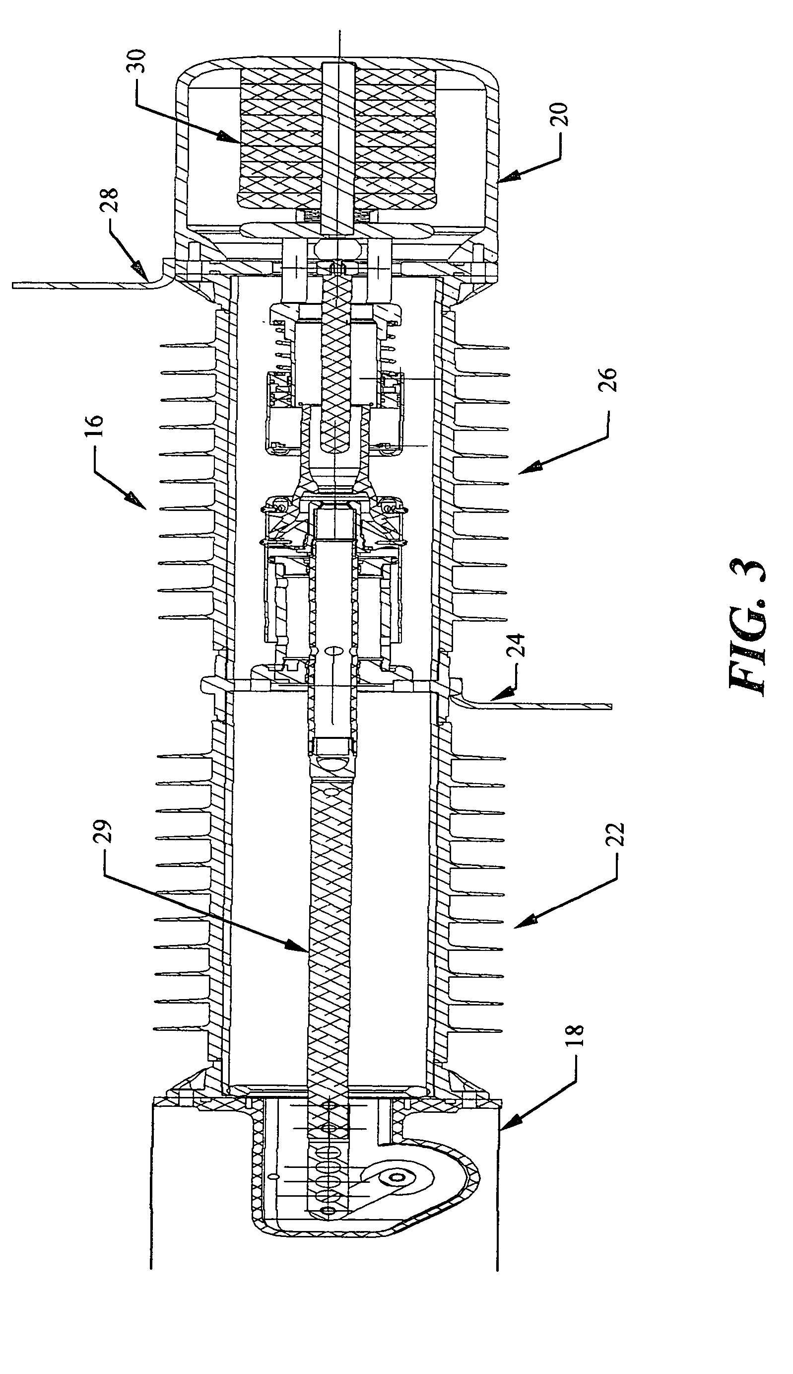
[0040]The present invention may be embodied in an electric power switch that is suitable for use as a capacitor switch at distribution and sub-transmission voltages. The capacitor switch typically includes a power contactor and an impedance contactor located within a relatively slender insulator forming a container filled with dielectric gas. The capacitor switch also includes a conductive cap housing a charging impedance located on the end of the insulator, which physically separates the conductive cap and the charging impedance from the insulator. This allows the conductive cap to be electrically separated from container, which allows the insulator to be replaced by a grounded conductive container in a “dead tank” configuration.

[0041]The power contactor may be a probe-and-socket type penetrating contactor, with a fixed probe and a moving socket. Similarly, the impedance contactor may be a ring-type butt contactor surrounding the penetrating contactor. The butt contactor typically ...


PUM


Abstract

A capacitor switch including a power contactor and an impedance contactor located within a relatively slender container filled with dielectric gas. The container may be a “dead tank” or an insulator. For the insulator configuration, the switch also includes a conductive cap housing a charging impedance located on the end of the insulator. The power contactor includes a relatively fixed probe contact and a linearly moving socket. The impedance contactor is ring-type butt contactor surrounding the penetrating contactor that includes a retracting (but otherwise fixed) contact that surrounds the fixed probe, and a traveling ring contact that surrounds and moves with the moving socket contact. The impedance contactor closes before the power contactor on the closing stroke to introduce the charging impedance into the circuit. A puffer mechanism retards the expansion of the retracting contact on the opening stroke, which causes the impedance contactor to open before the power contactor.

Description

TECHNICAL FIELD[0001]The present invention relates to electric switchgear and, more particularly, relates to an electric power switch, which is suitable for use as a capacitor switch at distribution and sub-transmission voltages, with a linear moving penetrating contactor and a retracting impedance contactor located inside a container filled with dielectric gas.BACKGROUND OF THE INVENTION[0002]Circuit breakers, line switches, disconnect switches and capacitor switches are well known components of electric transmission and distribution systems. Within these devices, spring-driven acceleration mechanisms have been used to accelerate penetrating contactors to sufficient velocity to extinguish an arcing contact occurring across a contactor gap within the switch without experiencing an undesirable restrike, which could otherwise cause disturbances on the electric power system. This typically requires extinguishing the arc after one-half cycle, which prevents a restrike from occurring aft...

Claims


Application Information

Patent Timeline
Patent Type & Authority Patents(United States)
IPC IPC(8): H01H9/42H01H33/16
CPCH01H33/166
Inventor ROSTRON, JOSEPH R.MCCORD, NEIL
Owner SOUTHERN STATES
Why Eureka
Try Eureka