Image forming apparatus

a technology of image forming apparatus and forming tube, which is applied in the direction of electrographic process apparatus, thin material handling, instruments, etc., can solve the problems of paper jamming, paper jamming, paper jamming, etc., and achieve the effect of efficient charge elimination effect of recording material

Active Publication Date: 2005-09-15
CANON KK
View PDF22 Cites 16 Cited by
  • Summary
  • Abstract
  • Description
  • Claims
  • Application Information

AI Technical Summary

Benefits of technology

[0010] The present invention has been made in consideration of the foregoing drawbacks and an object o

Problems solved by technology

In such prior technology, however, the leading end of the paper P may be caught by the charge eliminating brush 115 thereby causing a paper jam.
When a thin paper P contact the charge eliminating brush 115, a leading end portion may be bent thereby leading to a paper jamming.
The charge eliminating brush 115, constituting a charge elimination member in FIG. 7, is so position

Method used


Image

  • Image forming apparatus
  • Image forming apparatus
  • Image forming apparatus

Examples


first embodiment

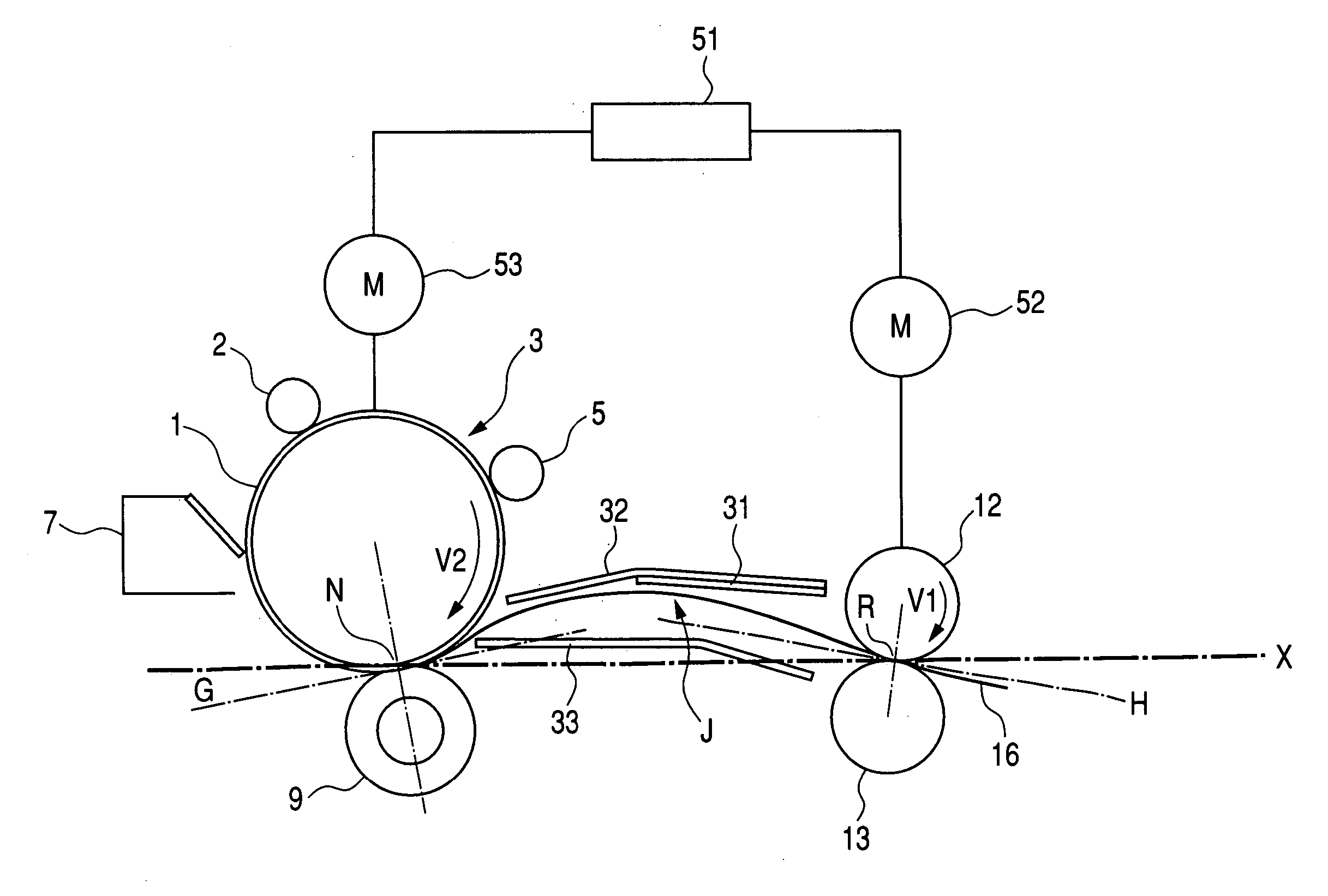
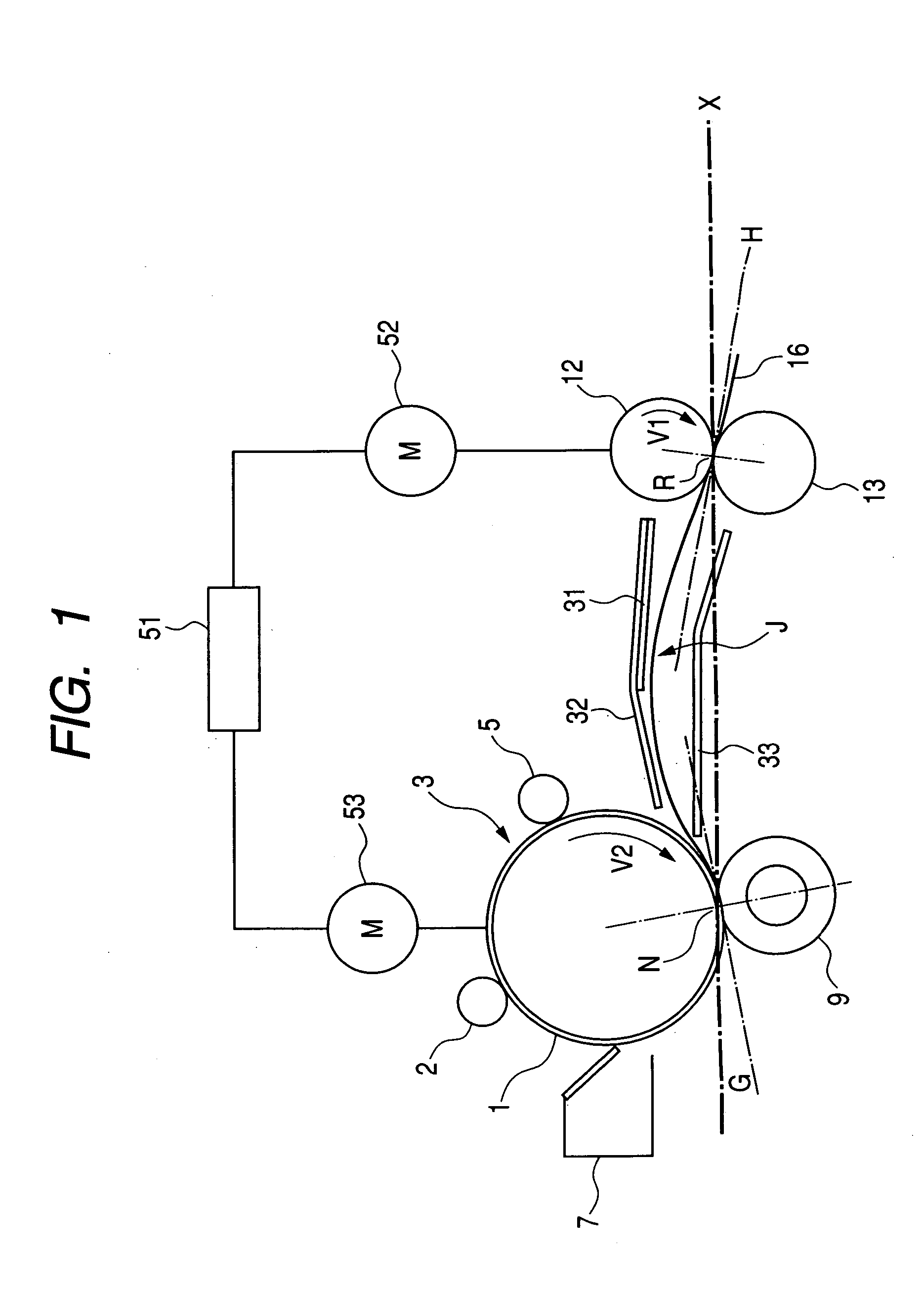
[0043]FIG. 1 illustrates a first embodiment of the present invention, wherein shown are a photosensitive drum 1 constituting an image bearing member; a transfer roller 9 constituting a transfer member; an upper registration roller 12; a lower registration roller 13; an upper guide 32 for limiting a conveying direction of the recording material in front of a transfer area; and a lower guide 33 for limiting a conveying direction of the recording material in front of the transfer area. The upper registration roller 12 and the lower registration roller 13 form a nip thereby functioning as a recording material conveying member. In FIG. 1, a line G is tangential to an external periphery of the photosensitive drum 1 and perpendicular to a line passing the centers of the photosensitive drum 1 and the transfer roller 9. Also a line H is perpendicular to a line passing the centers of the upper registration roller 12 and the lower registration roller 13 and tangential to the external periphery...

second embodiment

[0061]FIG. 3 shows a configuration of a second embodiment of the present invention. As the configuration is approximately same as that of the first embodiment, explanation will be given principally on different components. Components represented by same numbers as the components in the first embodiment have equivalent functions and will not, therefore, be explained again.

[0062] In the present embodiment, an upper guide 67 is provided with a recess in which provided a charge eliminating needle 65 constituting a charge elimination member. Paired registration rollers and a transfer roller 9 move in the same manner as in the first embodiment, so that the paper has a conveying path J similar to that in the first embodiment.

[0063] An upper guide 67 and a lower guide 66 are both electrically grounded. The charge eliminating needle 65 constituting the charge elimination member is constituted of charge eliminating needles with tips arranged with a pitch of 2 mm. The charge eliminating need...

third embodiment

[0071]FIG. 4 shows a third embodiment of the present invention.

[0072] The present embodiment shows an example where the present invention is applied to an apparatus in which paired registration rollers are positioned close to a photosensitive drum.

[0073] A configuration in which the paired registration rollers are close to the photosensitive drum can maintain the paper before the transfer in a waiting state in a position close to the photosensitive drum, thereby allowing to shorten the sheet conveying path and to reduce the dimension of the apparatus. In FIG. 4, there are shown a photosensitive drum 1 serving as an image bearing member and a transfer roller 9 serving as a transfer member, which forms a transfer nip in cooperation with the photosensitive drum 1, for transferring a toner thereon onto a paper. There are also shown a paper 16, a neutralizing cloth 31 constituting charge elimination member, an upper registration roller 34 and a lower registration roller 35 which are pa...


PUM


Abstract

The image forming apparatus includes an image bearing member for bearing a toner, a transfer device which forms a transfer area in cooperation with the image bearing member for transferring the toner on the image bearing member onto a recording material, a charge elimination device which is opposed to the recording material at an upstream side of the transfer area in a conveying direction of the recording material thereby eliminating a charge on the recording material, and a control device which controls the recording material so as to form a loop in a position opposed to the charge elimination device, wherein the recording material forms a loop by the control device thereby approaching to the charge elimination device. It achieve effecting an efficient charge eliminating for a recording material.

Description

BACKGROUND OF THE INVENTION [0001] 1. Field of the Invention [0002] The present invention relates to an image forming apparatus utilizing an electrophotographic technology, and more particularly to a charge elimination of a recording material. [0003] 2. Description of the Related Art [0004] A configuration of a prior image forming apparatus is shown in FIG. 7. [0005] A prior image forming apparatus is provided with a photosensitive drum 101 serving as an image bearing member. The photosensitive drum 101 is shaped in a cylindrical form, and is supported rotatably in a direction R1 indicated by an arrow, in a main body (not shown) of the apparatus. Along a periphery and a rotating direction of the photosensitive drum 101, there are provided, for example, a charging apparatus 102 for uniformly charging the photosensitive drum 101, an exposure apparatus 103 for emitting a laser beam corresponding to a document image (the image of an original) for exposing the photosensitive drum 101 the...

Claims


Application Information

Patent Timeline
IPC IPC(8): G03G15/00
CPCG03G2215/00649G03G15/657
Inventor YUMINAMOCHI, TAKAYASU
Owner CANON KK
Why Eureka
Try Eureka