Image forming apparatus

a technology of forming apparatus and forming plate, which is applied in the direction of electrographic process, instruments, transportation and packaging, etc., can solve the problems of weak electric field influence of the conveyance belt inability to eliminate the actual charge on the printing side of the sheet, and non-uniform electric field generation, etc., to achieve high-quality image and increase printing speed

Inactive Publication Date: 2009-09-22
RICOH KK
View PDF24 Cites 17 Cited by
  • Summary
  • Abstract
  • Description
  • Claims
  • Application Information

AI Technical Summary

Benefits of technology

[0018]In an aspect of the present disclosure, an image forming apparatus is provided which suppresses the deviation of the impact position of the ink drop and the adhering of the ink mist to the head discharge nozzle even if the conveyance speed of the sheet is raised to increase the printing speed, and is able to obtain the high quality image.
[0032]According to the present invention, the AC bias voltage is supplied to the conveyance unit so that the conveyance unit is charged alternately to one of positive polarity and negative polarity and the closed electric field on the conveyance belt is generated. The amount of charge on the printing surface of the recording sheet is decreased, and the positive charge and the negative charge are generated on the printing surface of the recording sheet so that both the charges are canceled by each other. Thereby, the charge on the printing side of the sheet is eliminated, and the occurrence of the electric field between the sheet and the head is suppressed.
[0033]Moreover, by the time the recording sheet is electrostatically attached to the conveyance unit and conveyed to the position where the sheet confronts the head, the charge eliminating unit eliminates the charge on the printing surface of the sheet. Thereby, even if the conveyance speed is increased to shorten the time for the sheet to arrive at the position and canceling the positive charge and the negative charge by each other is difficult, the charge eliminating unit eliminates the charge on the printing surface of the sheet. It is possible to eliminate most of the charge existing on the printing surface of the recording sheet even in such a case.
[0034]Accordingly, even if the conveyance speed is increased, it is possible to suppress the occurrence of the electric field between the recording sheet and the head unit by the elimination of the charge on the printing surface of the recording sheet by the charge eliminating unit and the elimination of the charge on the printing surface of the recording sheet by supplying the AC bias voltage to the conveyance unit.
[0035]This makes it possible to suppress the charging of the ink drop discharged from the head unit, the deviation of the impact position of the ink drop, or the backward flowing of the ink mist and adhering to the discharge nozzle of the head unit, which will interfere with the normal discharging of the ink by the head unit. Consequently, even if the high-speed printing is implemented, the high-quality image without disturbance in the image can be obtained.

Problems solved by technology

However, in the case of charging the conveyance belt alternately to one of the positive polarity and the negative polarity, a non-uniform electric field is generated in the perpendicular direction from the positive charge on the conveyance belt to the conveyance belt, but the electric field in the middle thereof is deviated toward the negative electric charge on the conveyance belt.
Since the electric field in the closed formation is generated on the conveyance belt, the influence of the electric field from the conveyance belt on the printing side of the sheet becomes weaker.
Conventionally, if the conveyance speed of the sheet is raised for improvement of the printing speed, the actual charge on the printing side of the sheet cannot be eliminated by the time the sheet arrives at the position where it confronts the head unit.
For this reason, there is the problem that the impact position of the ink drop is deviated, or the ink mist adheres to the head discharge nozzle, and it is difficult to obtain the high quality image with the conventional image forming apparatus.
Thereby, even if the conveyance speed is increased to shorten the time for the sheet to arrive at the position and canceling the positive charge and the negative charge by each other is difficult, the charge eliminating unit eliminates the charge on the printing surface of the sheet.

Method used


Image

  • Image forming apparatus
  • Image forming apparatus
  • Image forming apparatus

Examples


Embodiment Construction

[0058]A description will now be given of the preferred embodiments of the invention with reference to the accompanying drawings.

[0059]Hereinafter, the ink jet printer (also called the printer) will be explained as one preferred embodiment of the image forming apparatus in which the present invention is embodied.

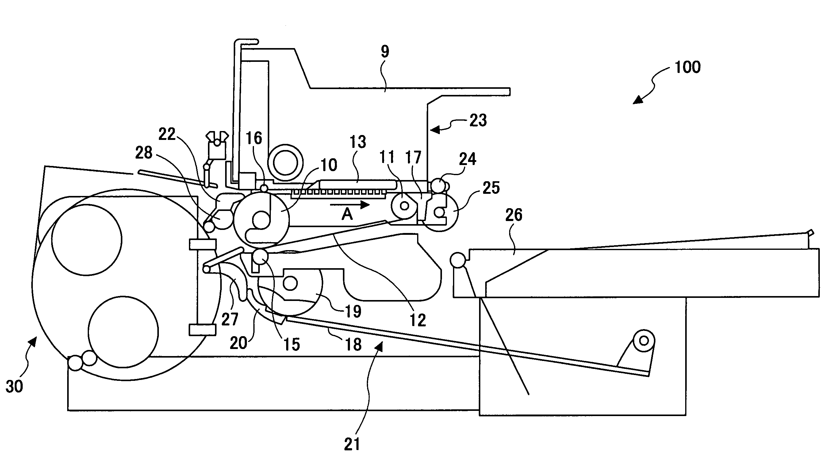
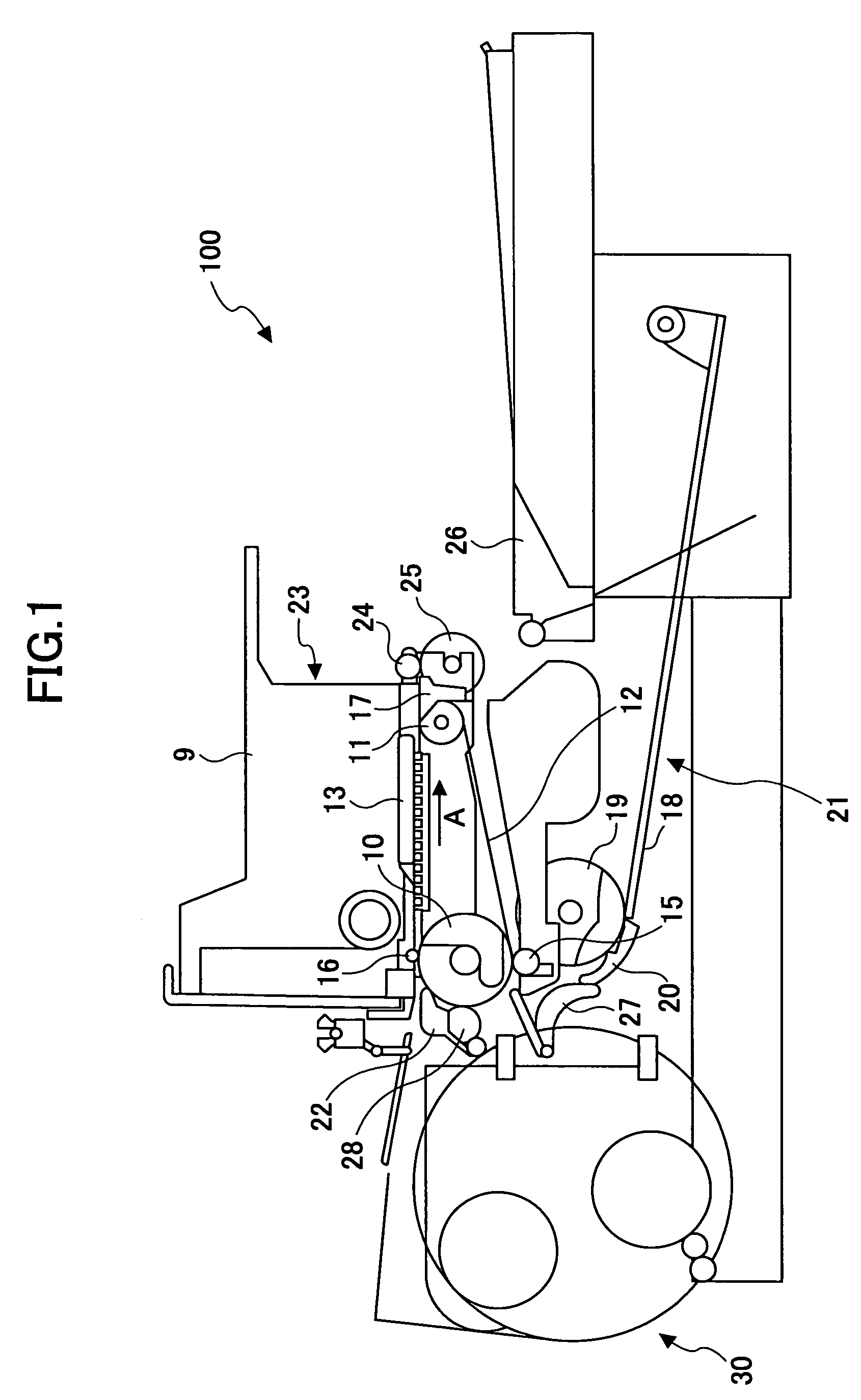
[0060]FIG. 1 shows the outline composition of the printer in the preferred embodiment of the invention.

[0061]As shown in FIG. 1, the printer 100 comprises the printing mechanism unit 23 which has the carriage 9 which is movably held. The carriage 9 is movable in the direction (the main-scanning line) perpendicular to the conveyance direction of the recording sheet by means of the drive unit (which is not illustrated). Moreover, the printer 100 comprises the conveyance unit 21 which conveys the sheet from the sheet feeding tray 18 to the ejection tray 26 via the position where the sheet confronts the printing mechanism unit 23.

[0062]The printing head 13 which has the discharge...


PUM

PropertyMeasurementUnit
lengthaaaaaaaaaa
volume resistivityaaaaaaaaaa

Abstract

In an image forming apparatus, an AC bias is supplied to a conveyance belt, and the amount of charge on the printing side of a recording sheet is decreased. The charge of positive polarity and the charge of negative polarity which are different from each other are generated on the printing side of the sheet, so that both the charges are cancelled by each other and the charge on the printing side of the sheet is eliminated. Moreover, the charge eliminator eliminates the charge on the printing side of the sheet by the time the sheet is electrostatically attached to the conveyance belt and conveyed to a position where the sheet confronts the head.

Description

TECHNICAL FIELD[0001]The present invention relates to an image forming apparatus which comprises a head unit having a discharge nozzle for discharging an ink, and a conveyance unit confronting the head unit and conveying a recording sheet to a position where it confronts the head unit wherein the head unit discharges the ink from the discharge nozzle to the sheet so that an image is printed on the recording sheet.BACKGROUND ART[0002]Conventionally, the ink jet printer is known as an image forming apparatus which discharges the ink drop from the discharge nozzle of the head unit and forms an image on the recording sheet from the paper cassette.[0003]In the ink jet printer, the ink drop discharged from the discharge nozzle directly reaches the sheet and the image is printed on the sheet. For this reason, in order to realize high quality of the image, it is necessary to raise the accuracy of positioning the ink drop on the recording sheet.[0004]There have been some conceivable methods ...

Claims


Application Information

Patent Timeline
Patent Type & Authority Patents(United States)
IPC IPC(8): B41J2/01B41J11/00B41J29/00B41J29/38B65H5/00B65H5/02
CPCB41J3/60B41J11/0015B41J11/002B41J11/007B41J13/0045B65H5/004B65H5/025B41J29/38B65H2301/5321B65H2301/44334B65H2301/5133B41J11/00244B41J2/2132
Inventor IMOTO, SHINJIITO, YOICHIKOGURE, SEIICHI
Owner RICOH KK
Why Eureka
Try Eureka