

Image forming apparatus
a technology of image forming apparatus and forming tube, which is applied in the direction of electrographic process apparatus, instruments, optics, etc., can solve the problems of density unevenness in the final toner image, overall size of the apparatus,
- Summary
- Abstract
- Description
- Claims
- Application Information
AI Technical Summary
Benefits of technology
Problems solved by technology
Method used
Image

Examples
first embodiment
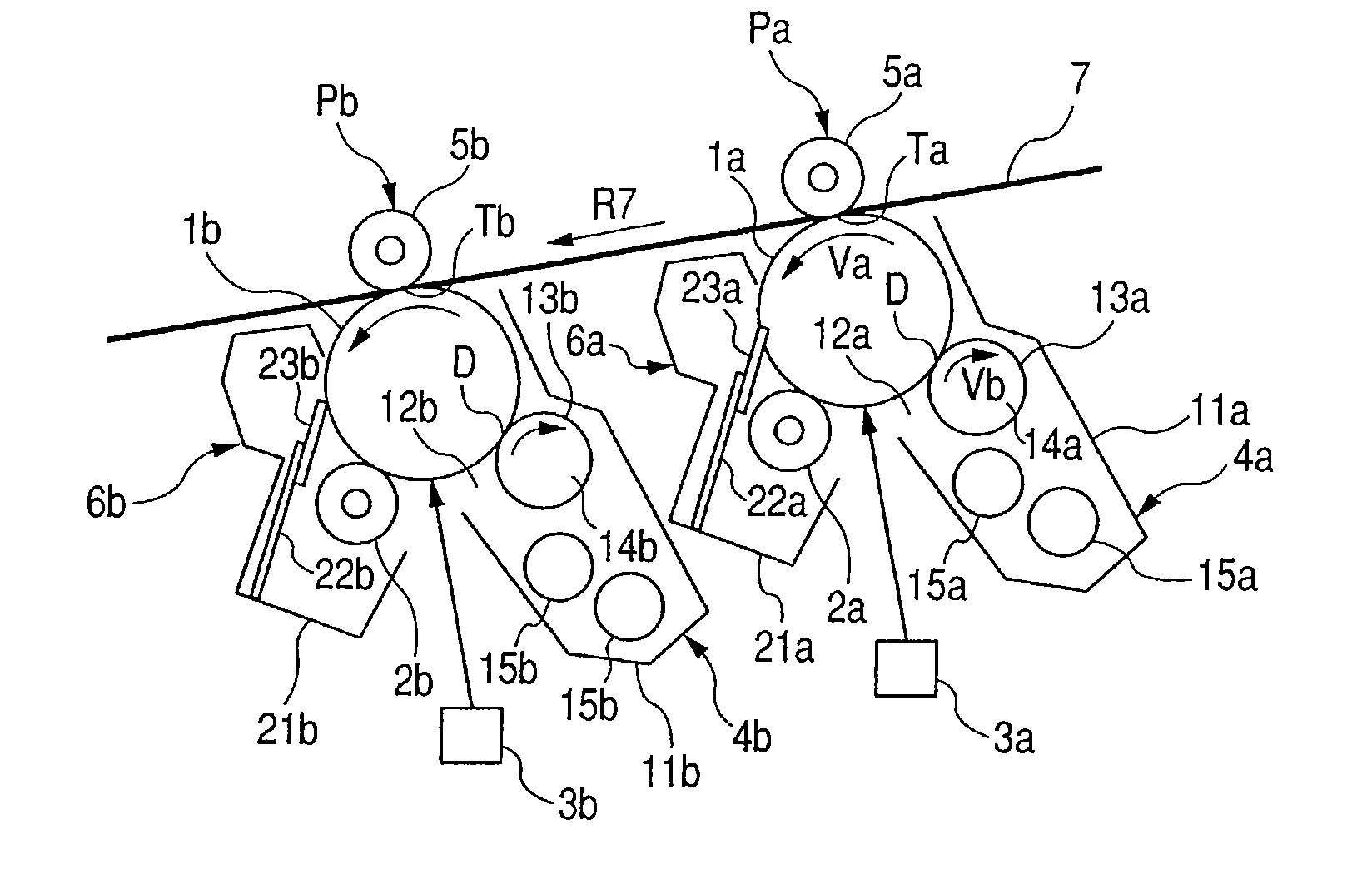
[0021]FIG. 1 shows a part of an image forming apparatus to which it is possible to apply the present invention. The image forming apparatus in the figure is an image forming apparatus adopting an electrophoto system, a tandem system, and an intermediate transferring member system and a part of a general construction of the image forming apparatus is schematically shown in the figure.
[0022]The image forming apparatus includes an intermediate transferring belt 7 that is an intermediate transferring member and a first image forming unit (image forming means) Pa is arranged of an upstream side along a rotation direction of the intermediate transferring belt 7 (direction of an arrow R7). Also, a second image forming unit (image forming means) Pb is arranged of a downstream side.
[0023]In the image forming units Pa and Pb, photosensitive drums 1a and 1b that are image bearing members are respectively arranged. Around the photosensitive drums 1a and 1b, charging rollers 2a and 2b that are c...
second embodiment
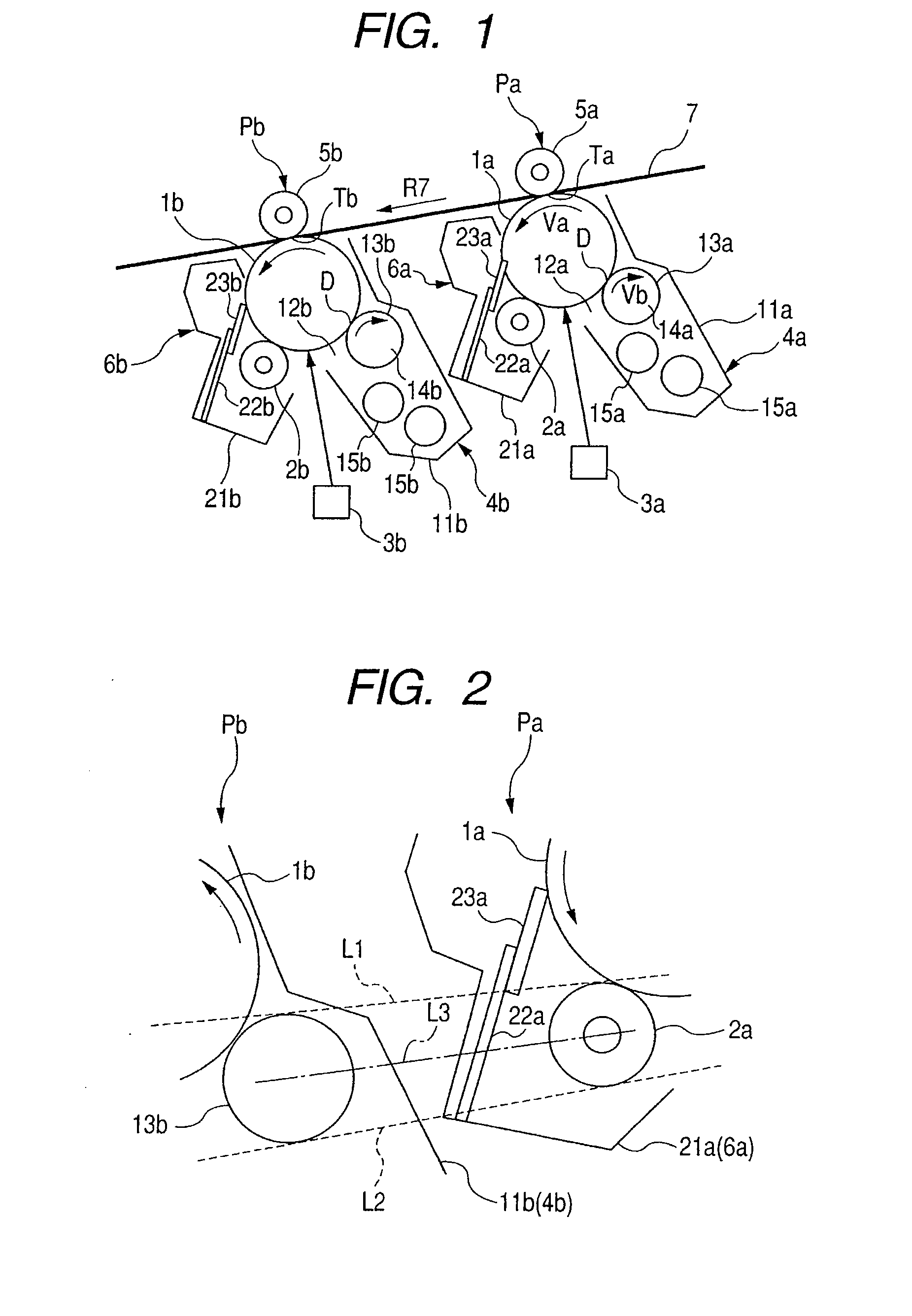
[0044]FIG. 4 shows a second embodiment of the present invention. In this embodiment, a base-end-side portion of the support member that supports the cleaning blade is folded to cover the charging roller.
[0045]In order to obtain a sufficient shielding effect with the support member, it is required that the support member completely shield tangents L1 and L2 between the charging roller 2a and the developing sleeve 13b as described above.
[0046]When a base-end portion 25a3 of a support member 25a that supports the cleaning blade 23a is extended in a straight line manner in accordance with a tip-end portion 25a2 as shown in FIG. 4, however, there is a fear that interference with the developing container 11b of the image forming unit Pb of the downstream side will occur. Also, when the distance between the image forming units Pa and Pb is increased in order to prevent the interference, the overall size of the image forming apparatus increases.
[0047]Therefore, in this embodiment, in order ...
third embodiment
[0052]FIG. 5 shows a third embodiment of the present invention. A support member 27a in this embodiment is constructed so that a base-end portion 27a3 is folded in a folding portion 27a1 with respect to a tip-end portion 27a2 and is extended to go under the charging roller 2a and a container 28a positioned in an outer peripheral portion of the charging roller 2a is covered with the support member 27a. Note that the container 28a is a part of a cleaning container 24a.
[0053]The charging roller 2a is pressurized and abutted against the surface of the photosensitive drum 1a through energization of metal core portions (not shown) in both end portions in a lengthwise direction toward the photosensitive drum 1a by a pressurizing member (not shown) such as a spring.
[0054]Here, when it is desired to further reduce the size of the image forming apparatus, it is effective to reduce the distance between the charging roller 2a and the container 28a. Under such a positional relation, there is a ...
PUM
 Abstract
Description
Claims
Application Information