Connector assemblies and methods of manufacture

a technology of connecting parts and connectors, applied in the direction of unstripped conductor connection apparatus, coupling device connection, contact member penetrating/cutting insulation/cable strands, etc., can solve the problem of copper insulation displacement member corroding

Active Publication Date: 2017-01-17
CORNING OPTICAL COMM LLC
View PDF1148 Cites 71 Cited by
  • Summary
  • Abstract
  • Description
  • Claims
  • Application Information

AI Technical Summary

Benefits of technology

[0007]In accordance with one embodiment, a connector assembly may comprise a connector framework and at least one insulation displacement member. The connector framework may comprise an insulated-wire passage that is sized and oriented to receive an insulated electrically conductive wire. The insulation displacement member may comprise a conductive wire engaging portion and may be mechanically supported by the connector framework to permit forcible engagement of the wire engaging portion with the insulated electrically conductive wire. The insulation displacement member may define an electrically conductive path extending from the wire engaging portion to an electrical coupling node of the connector assembly. At least the wire engaging portion of the insulation displacement member may be coated with a cured hydrophobic organosilane mono-layer protective coating such that may seals the insulation displacement member from environmental moisture or otherwise protect the insulation displacement member from damage.

Problems solved by technology

For example, a copper insulation displacement member may corrode over time when exposed to moisture.

Method used


Image

  • Connector assemblies and methods of manufacture
  • Connector assemblies and methods of manufacture
  • Connector assemblies and methods of manufacture

Examples


Embodiment Construction

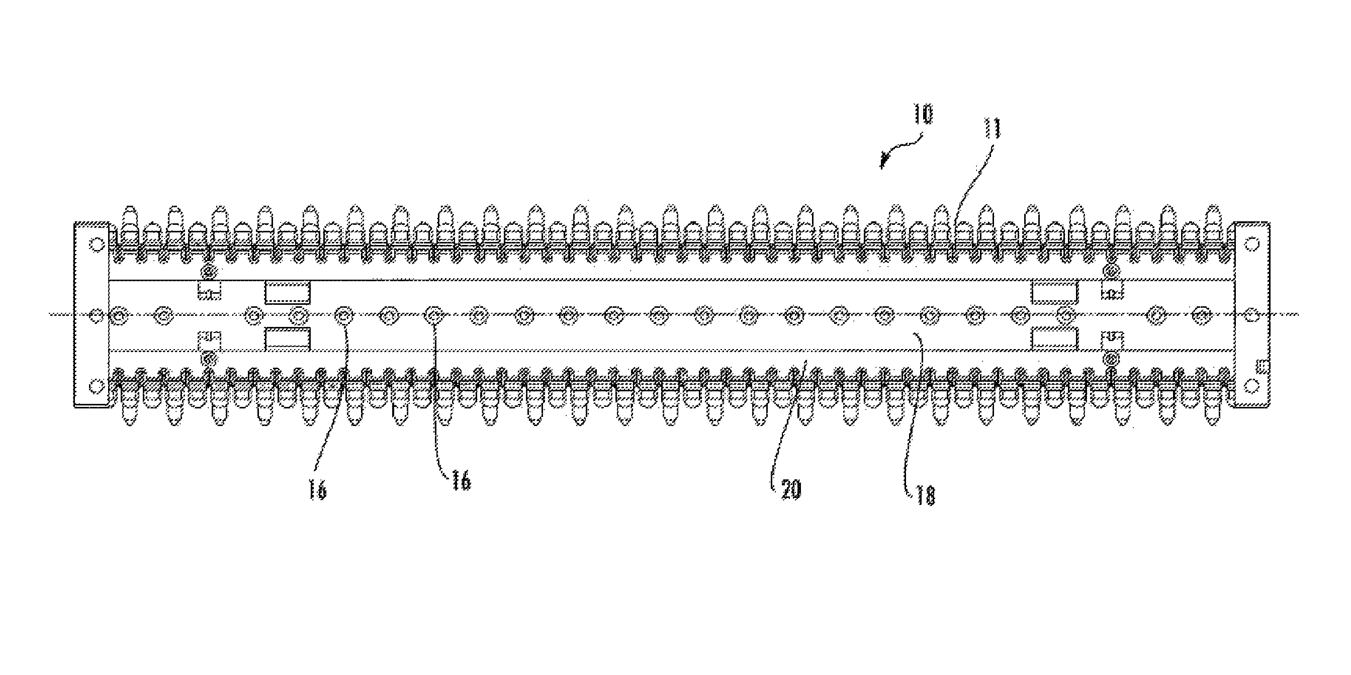
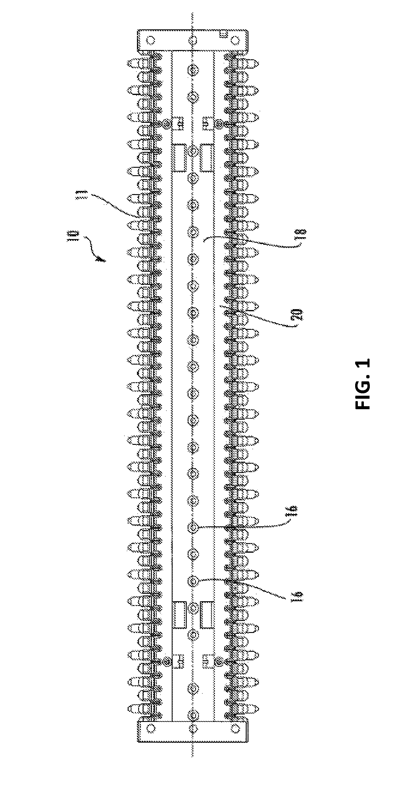
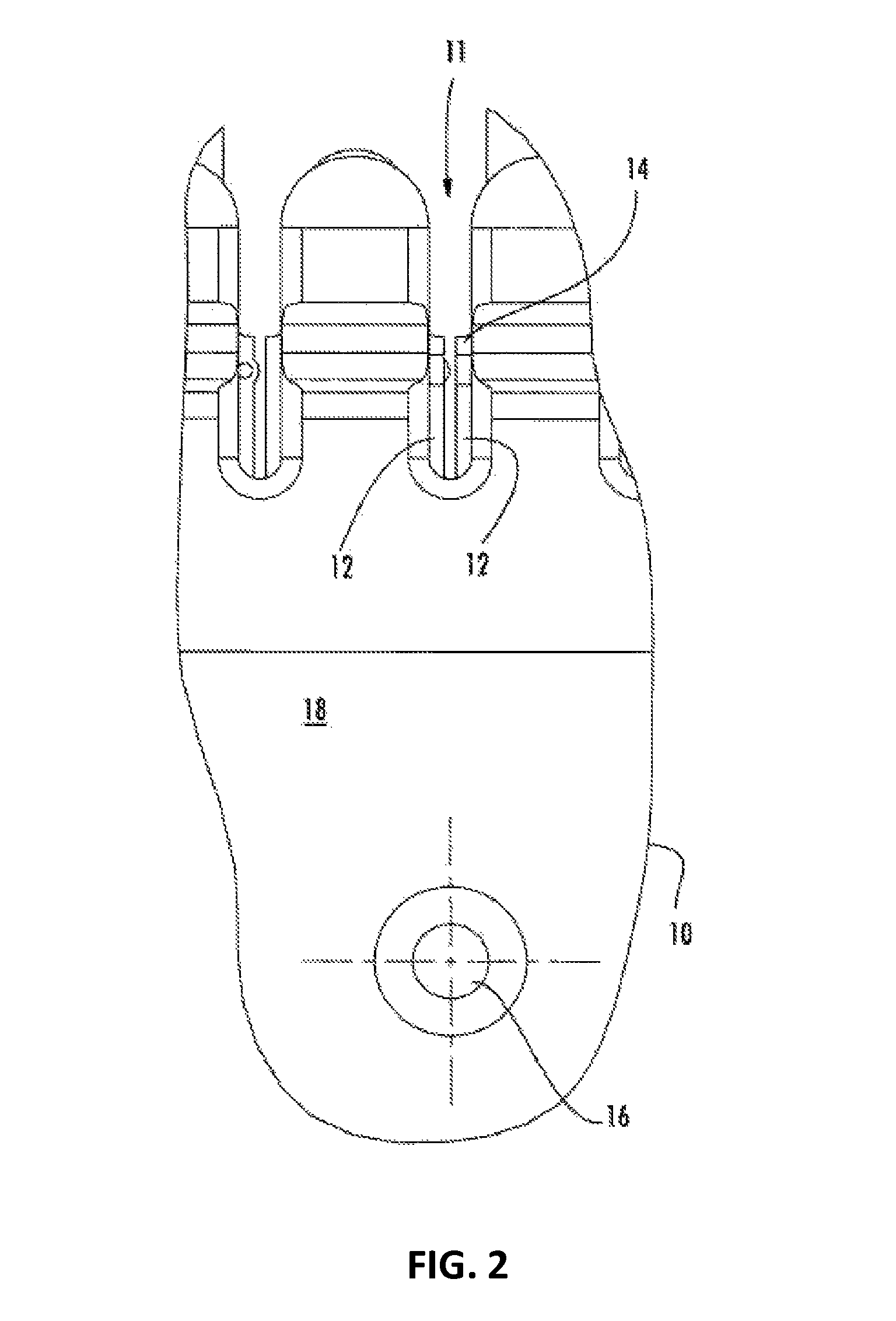
[0015]Reference will now be made in greater detail to various embodiments, some embodiments of which are illustrated in the accompanying drawings. Whenever possible, the same reference numerals will be used throughout the drawings to refer to the same or similar parts. Generally, disclosed herein are various embodiments of connector assemblies and their methods of manufacture. A connector assembly may comprise a connector framework and at least one insulation displacement member. As described herein, at least a portion of the insulation displacement member may have a protective coating. In one embodiment, the protective coating is a cured hydrophobic organosilane mono-layer protective coating. The protective coating seals the insulation displacement member from environmental moisture or otherwise protects the insulation displacement member.

[0016]FIGS. 1 and 2 illustrate a connector assembly 10 comprising at least one insulation displacement member 12. For example, the connector asse...


PUM

PropertyMeasurementUnit
temperatureaaaaaaaaaa
thicknessaaaaaaaaaa
temperatureaaaaaaaaaa

Abstract

A connector assembly that includes an insulation displacement member including a hydrophobic organosilane mono-layer protective coating is disclosed. In one embodiment, the connector assembly may be manufactured by a method that includes assembling the connector assembly, contacting the connector assembly with an organosilane coating solution, and curing the organosilane coating solution. The connector assembly may be assembled by mechanically supporting the insulation displacement member with a connector framework. The connector assembly may be contacted with the organosilane coating solution by contacting at least the wire engaging portion of the insulation displacement member and at least a portion of the connector assembly with the organosilane coating solution.

Description

BACKGROUND[0001]Field[0002]The subject matter of the present disclosure generally relates to electrical connectors comprising insulation displacement members.[0003]Technical Background[0004]Electrical circuits, and in particular telecommunications networks, make extensive use of electrical connectors, sometimes referred to herein as connector assemblies, to quickly and easily establish electrical connections with insulated electrical conductors, such as insulated wires. For example, electrical connections need to be established between a service provider, such as a telephone company or an internet service provider, and the subscriber. In telecommunications networks, electrical connectors are typically disposed within wire termination devices, such as line modules, protected terminal devices, and station protectors, and establish the necessary electrical connections throughout the network.[0005]Some electrical connectors utilize insulation displacement type connectors, which contain ...

Claims


Application Information

Patent Timeline
Patent Type & Authority Patents(United States)
IPC IPC(8): H01R4/24H01R43/00H01R13/52H01R43/18H01R13/03H01R43/01H01R9/24
CPCH01R13/5221H01R4/2404H01R13/03H01R43/005H01R43/18H01R4/2429H01R9/24H01R43/01Y10T29/4922C09D183/04
Inventor LIU, ZIWEI
Owner CORNING OPTICAL COMM LLC
Why Eureka
Try Eureka