
Sport helmet

a helmet and helmet technology, applied in the field of sports helmets, can solve the problems of helmets being less comfortable in warm weather, non-optimal aerodynamics,

Active Publication Date: 2017-03-07
LOUIS GARNEAU SPORTS
View PDF15 Cites 4 Cited by
  • Summary
  • Abstract
  • Description
  • Claims
  • Application Information

AI Technical Summary

Problems solved by technology

Helmets have been shown to be non-optimal in terms of aerodynamics, notably because of the presence of such vents causing additional drag.
However, such helmets may not be as comfortable in warm weather.

Method used


Image

  • Sport helmet
  • Sport helmet
  • Sport helmet

Examples


Embodiment Construction

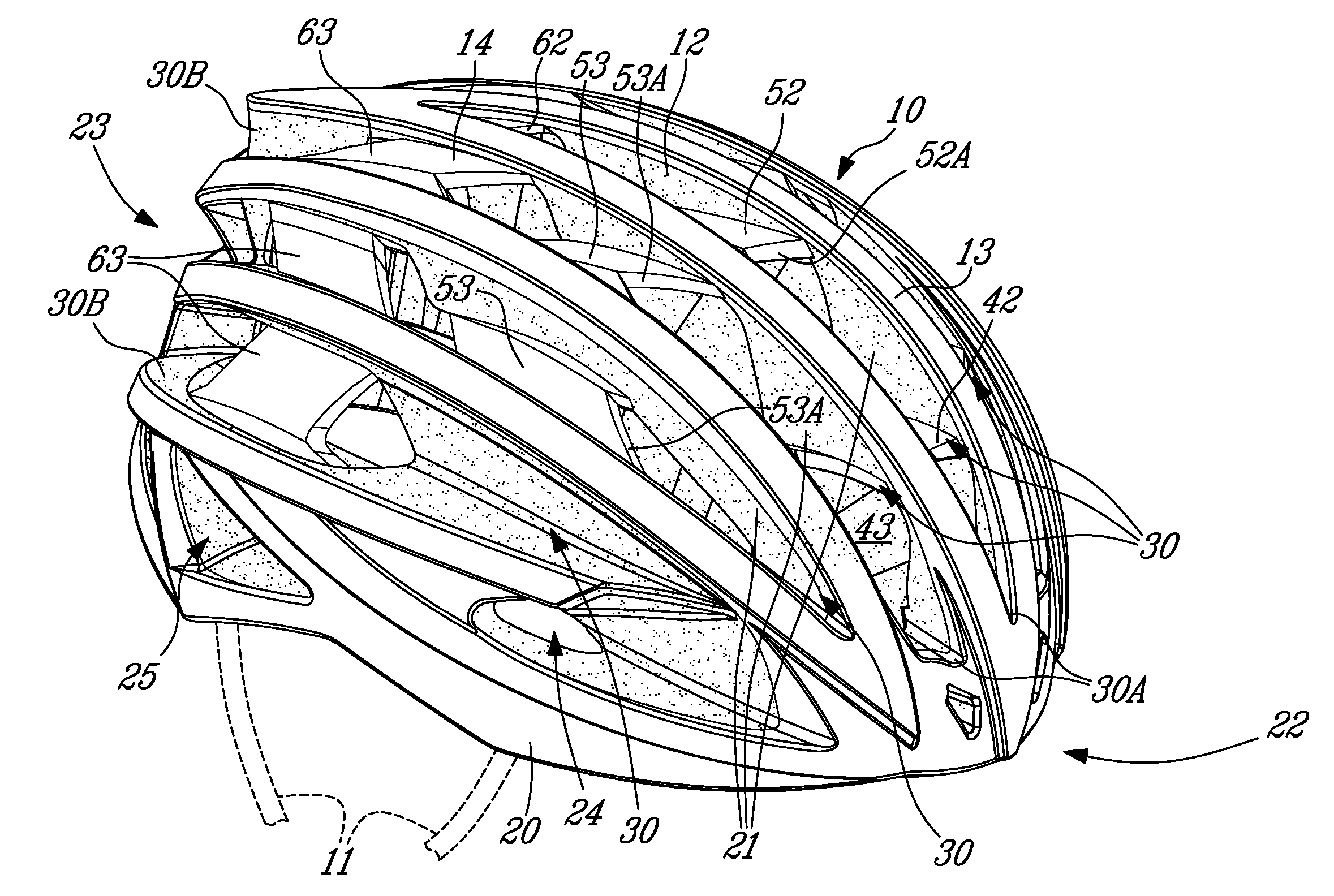
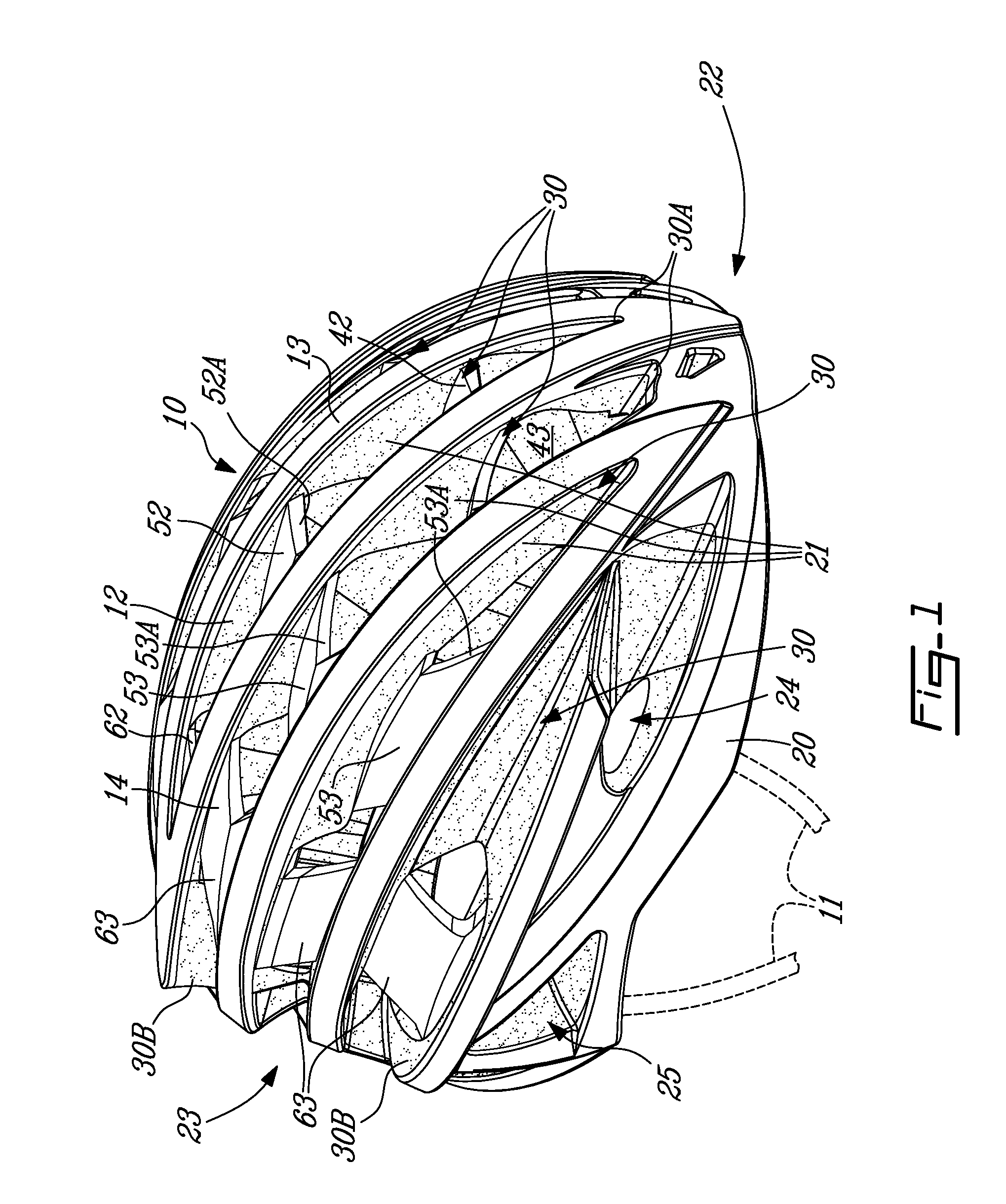
[0012]Referring to the drawings, and more particularly to FIG. 1, there is illustrated a helmet 10 in accordance with the present disclosure. The helmet 10 is of the type that is used for bicycling and like sporting activities.

[0013]For simplicity, an attachment system is only summarily shown as 11. The attachment system is typically anchored to an interior of the helmet and features straps for the helmet to be strapped to the user's head. The attachment system may also comprise rigid attachment components in the rear of the helmet, to adjust the helmet to a circumference of the wearer's head. Hence, although summarily shown, the helmet 10 has such attachment means of any appropriate form.

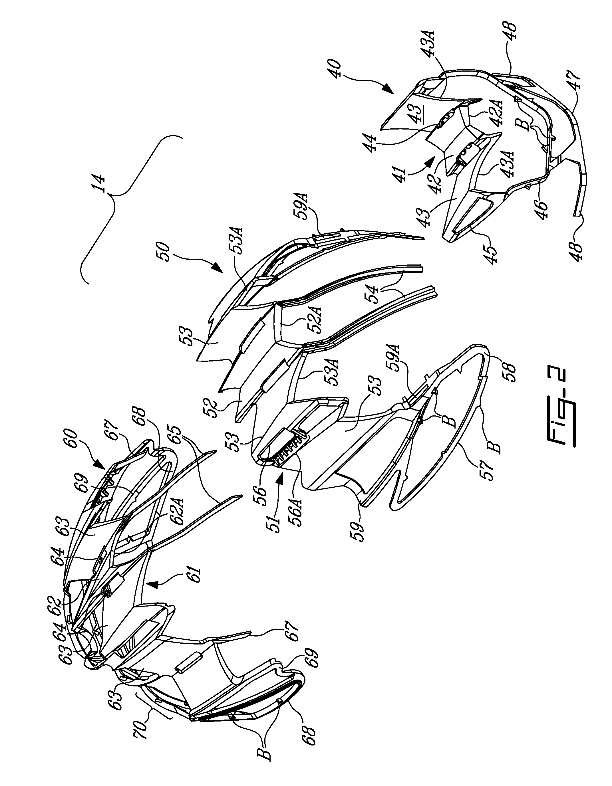
[0014]Referring concurrently to FIGS. 1, 2 and 3, the helmet 10 has a generally hemispherical shape formed by an inner liner 12, an outer shell 13 and a cage 14. By its hemispherical shape, the helmet 10 has an inner concave surface and outer convex surface, with the top and side of the wearer's he...


PUM


Abstract

A helmet has an inner liner made of foam material forming a body of the helmet. The inner liner has a convex outer surface and a concave inner surface defining a cavity for receiving the wearer's head. The inner liner has a plurality of beams extending from front to rear of the helmet and spaced apart to form vents therebetween, the vents being free of foam material between adjacent beams. Rigid bridge members are comolded with the inner liner to be partially concealed in the inner liner, the at least one bridge member having at least one bridge projecting out of the foam material of two adjacent beams and extending transversely in at least one of the vents. At least one strap is provided to attach the helmet to a wearer's head.

Description

TECHNICAL FIELD[0001]The present application relates to sport helmets, such as bicycle helmets.BACKGROUND OF THE ART[0002]Bicycle helmets have now become ubiquitous for the bicycling activity. In road and urban riding, one specific helmet construction has become the norm: that consisting of the foam inner liner with an outer shell. The inner liner forms the body of the helmet in terms of volume and structural integrity. The inner liner is typically made of a structural foam material such as expanded polystyrene. An outer shell covers the liner and defines the smooth and decorative exposed outer surface of the helmet. The outer shell and liner are most often co-molded. Other components include the attachment system inside the outer shell, by which the helmet is secured to the user's head.[0003]The above-referred configuration is quite convenient in terms of providing suitable head protection, while being lightweight. Moreover, in some instances, numerous vents may be defined in the h...

Claims


Application Information

Patent Timeline
Patent Type & Authority Patents(United States)
IPC IPC(8): A42B3/06
CPCA42B3/062A42B3/066
Inventor GARNEAU, LOUISHAMEL, DOMINIC
Owner LOUIS GARNEAU SPORTS
Learn More