Measurement apparatus, lithography apparatus, and article manufacturing method

a technology of lithography and measurement apparatus, which is applied in the direction of photomechanical apparatus, instruments, printing, etc., can solve the problems of deteriorating measurement accuracy, device cannot be offset, and difficult to eliminate relative fluctuation between the stage and the measurement device, so as to reduce the fluctuation of a relative position and improve measurement accuracy

Active Publication Date: 2017-05-16
CANON KK
View PDF4 Cites 0 Cited by
  • Summary
  • Abstract
  • Description
  • Claims
  • Application Information

AI Technical Summary

Benefits of technology

[0008]The present invention provides a measurement apparatus having advantages in measurement accuracy and measurement time period. The present invention provides a measurement apparatus for measuring a position of a mark on a stage, the apparatus comprising: an imaging unit positioned with fixing with respect to a first member and configured to sense an image of the mark; a first detector configured to detect a position of the stage with reference to a second member; a second detector configured to detect fluctuation of a position of the first member with reference to the second member; and a control unit configured to obtain the position of the mark from an image of the mark by the imaging unit while controlling a relative position of the stage relative to the second member so as to reduce fluctuation of a relative position of the mark relative to the imaging unit due to the fluctuation of the position of the first member based on a detection result of the first detector and a detection result of the second detector.

Problems solved by technology

If the stage where the mark is placed and the measurement device for the mark position are not supported by an identical housing, it is difficult to eliminate relative fluctuation between the stage and the measurement device due to vibrations of a floor.
Consequently, the relative fluctuation between the stage and the measurement device during a time period of fetching the image signals causes deterioration of the measurement accuracy.
To the contrary, in the case of having a longer relative fluctuation period between the stage and the measurement device than the time period of fetching the image, a fluctuation component between the stage and the measurement device cannot be offset even if the average position of the mark is found; thus the measurement accuracy of the mark position is not enhanced.
It may be considered to increase a frequency of the measurement of the stage position in accordance with the relative fluctuation period between the stage and the measurement device, which makes the measurement time period longer, resulting in deterioration of productivity in the apparatus.

Method used


Image

  • Measurement apparatus, lithography apparatus, and article manufacturing method
  • Measurement apparatus, lithography apparatus, and article manufacturing method
  • Measurement apparatus, lithography apparatus, and article manufacturing method

Examples


Embodiment Construction

[0015][Exposure Apparatus]

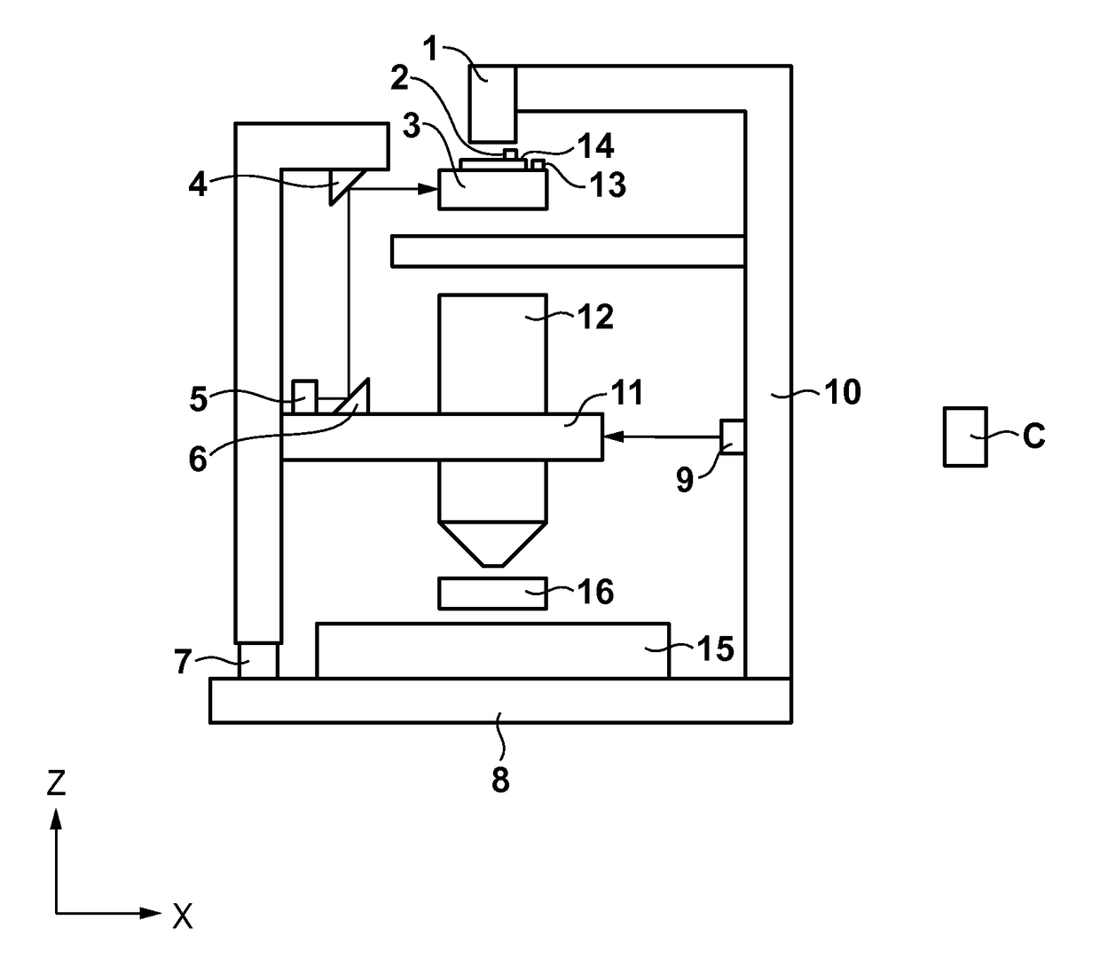
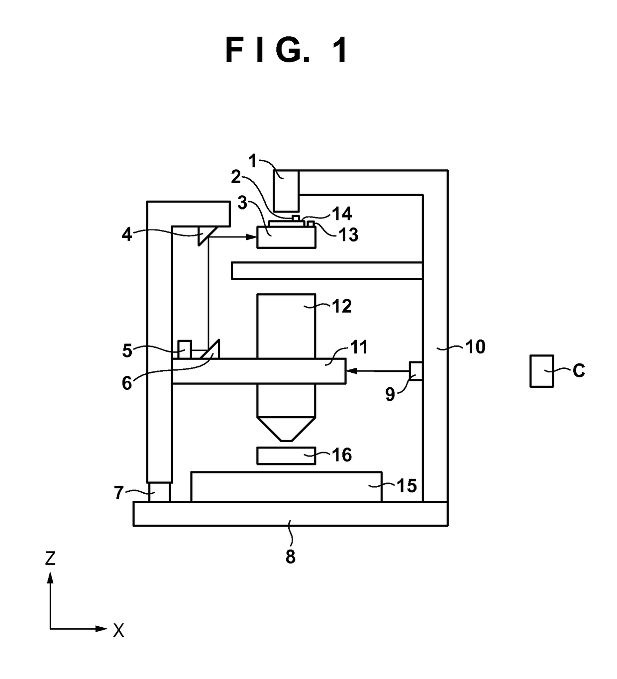
[0016]FIG. 1 is a schematic plan view of an exposure apparatus according to the present embodiment. In FIG. 1, a CCD camera (imaging unit) 1 senses an image of a mark 13 placed on a reticle stage (original stage) 3, or an image of a mark 2 placed on an object (reticle, original) 14. The imaging unit 1 is fixed to and positioned with respect to a base frame 10 (first member). A projection optical system 12 is supported by an optical system support (second member) 11. An active mount 7 supports the optical system support 11 while suppressing vibrations of the optical system support 11, and also isolates vibrations from the floor. A base 8 supports the active mount 7. Fixed mirrors 4, 6 are fixed to the optical system support 11 to be used for measuring a position of the reticle stage 3. A laser interferometer (first detector) 5 is fixed to the optical system support 11 to detect a position X of the reticle stage 3 with reference to the optical system support ...


PUM

PropertyMeasurementUnit
timeaaaaaaaaaa
frequencyaaaaaaaaaa
displacement meteraaaaaaaaaa

Abstract

A measurement apparatus includes: an imaging unit positioned with fixing with respect to a first member; a first detector configured to detect a position of a stage with reference to a second member; a second detector configured to detect fluctuation of a position of the first member with reference to the second member; and a control unit configured to obtain the position of the mark from an image of the mark sensed by the imaging unit while controlling a relative position of the stage relative to the second member so as to reduce fluctuation of a relative position of the mark relative to the imaging unit due to the fluctuation of the position of the first member based on detection results of the first and second detectors.

Description

BACKGROUND OF THE INVENTION[0001]Field of the Invention[0002]The present invention relates to a measurement apparatus, a lithography apparatus, and an article manufacturing method.[0003]Description of the Related Art[0004]Recently, exposure apparatuses have undergone progress of refinement of exposure accuracy, and have been strictly required for accuracy in positioning at the same time. In measurement for positioning, an image of a mark placed on a reticle that is an original is fetched by a measurement device for a mark position, such as a CCD camera, and the mark position is measured by processing the fetched image signals with a measurement apparatus. Hence, it is optimum to keep the measurement device for measuring the mark position and the mark in a state free from minute fluctuation due to vibrations or the like during performing the measurement for the positioning.[0005]If the stage where the mark is placed and the measurement device for the mark position are not supported b...

Claims


Application Information

Patent Timeline
Patent Type & Authority Patents(United States)
IPC IPC(8): G03B27/62G01B11/00G03F7/20
CPCG03F7/70775G01B11/002G03F7/70725
Inventor NODA, KENJI
Owner CANON KK
Why Eureka
Try Eureka