Eureka AIR delivers breakthrough ideas for toughest innovation challenges, trusted by R&D personnel around the world.
Interchangeable drum bearing edge rings
What is Al technical title?
Al technical title is built by PatSnap Al team. It summarizes the technical point description of the patent document.
a technology of edge rings and drum shells, applied in the direction of instruments, percussion musical instruments, instruments, etc., can solve the problem of needing a thicker drum shell
Active Publication Date: 2017-05-16
MARTIN AUGUST D
View PDF10 Cites 3 Cited by
Summary
Abstract
Description
Claims
Application Information
AI Technical Summary
This helps you quickly interpret patents by identifying the three key elements:
Problems solved by technology
Method used
Benefits of technology
[0013]It is an objective to provide a drum structural framework that disburses energy from the drumhead to a freely resonating drum shell while reducing or completely isolating the same energy from reverberating throughout the structural framework. It is therefore an objective to provide a drum structural framework that achieves a pure drum sound profile in which the resonance of the drum shell is unimpeded and distortion and other undesired sounds from the structural framework are eliminated.
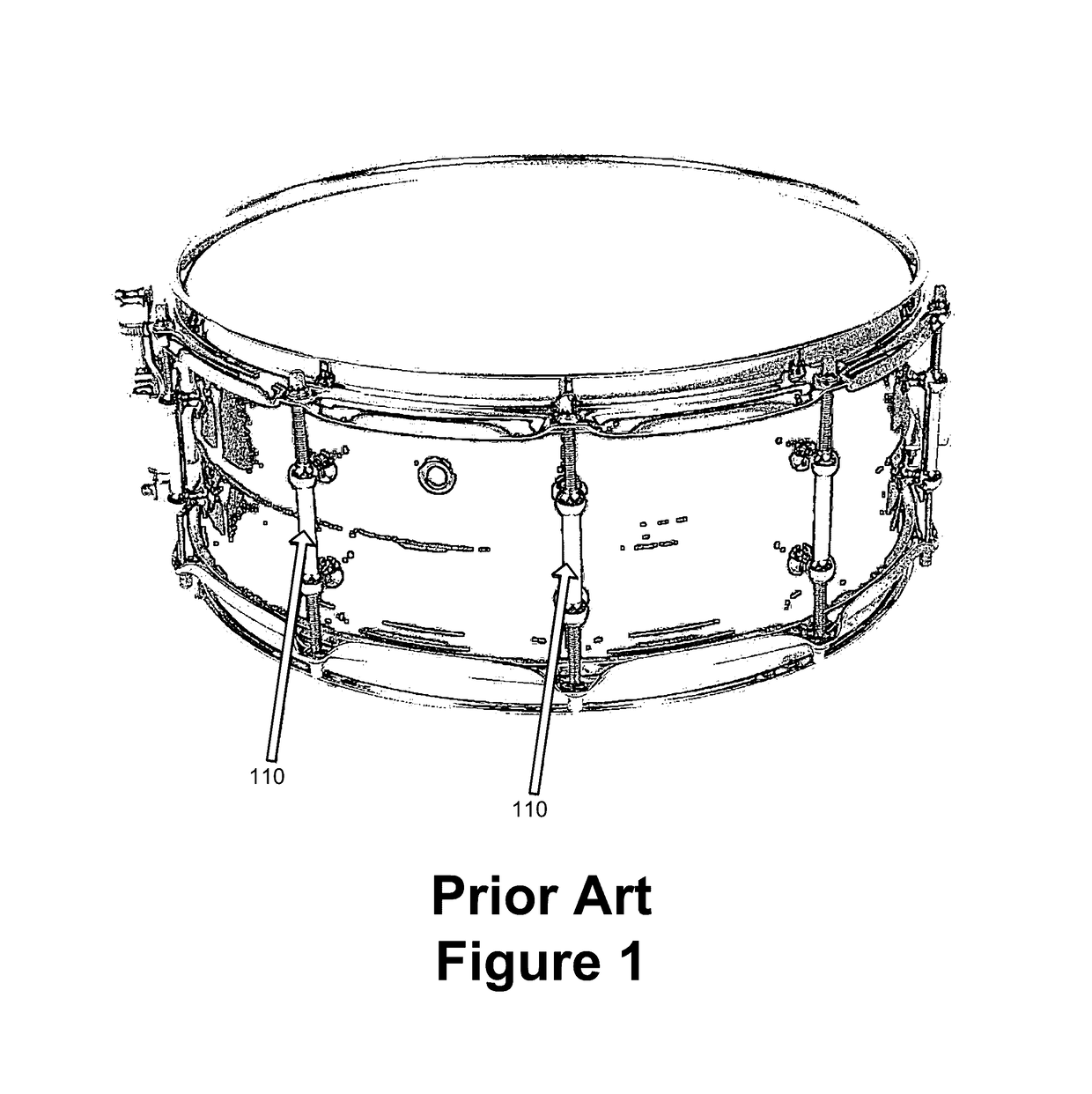
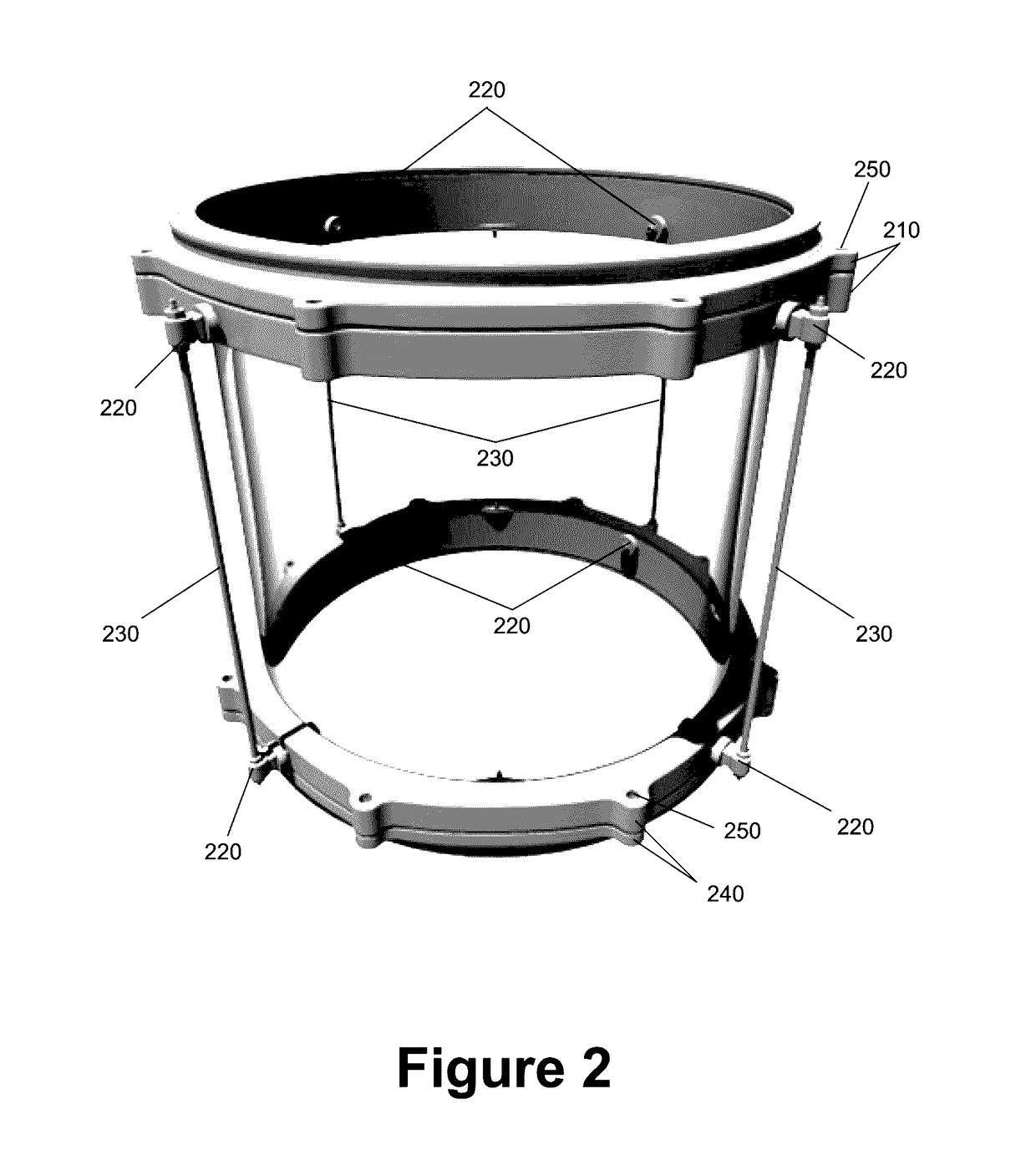
[0015]The top shell mount comprises a die-cast hoop, a bearing edge ring, and a tension ring. The top shell mount secures and tunes a first drumhead of the drum to the drum shell without hindering resonance of the drum shell. The bottom shell mount comprises a complementary die-cast hoop, bearing edge ring, and tension ring that secures and tunes a second drumhead also without hindering resonance of the shell. Specifically, a first set of the rod holders are coupled to the top shell mount and an aligned second set of the rod holders are coupled to the bottom shell mount. The tension rods link the first set of the rod holders to the corresponding second set of rod holders. Tuning assemblies on the rod holders can be used to adjust the distance separating the top shell mount from the bottom shell mount, thereby controlling the compression force imposed on the drum shell. The compression force holds the drum shell in place without hindering resonance of the drum shell, because the drum shell itself is only contacted along its top and bottom distal edges by the underside of the top shell mount and the bottom shell mount. The free resonance of the drum shell produces a richer and fuller sound profile as compared to other designs in which extraneous forces placed on the drum shell deaden the sound by obstructing the resonance of the drum shell. These extraneous forces typically manifest when lug holders or other forces are disposed along the side of the drum shell. An additional undesired byproduct of these extraneous forces is the need for a thicker drum shell. The greater the thickness of the drum shell, the greater the amount of energy needed to induce resonance and produce sound. However, since the design advocated herein removes any such extraneous forces from the drum shell, thinner drum shells or drum shells using less dense materials that were previously inapt, such as plastic, clay, and glass, can now be used. Consequently, a new evolution in drum sound is opened.
[0016]Moreover, each rod holder couples to either the top shell mount or bottom shell mount with one or more isolation rings that serve as vibration dampeners. The dampeners isolate energy passing from the drumhead to the drum shell from also reverberating throughout the structural framework of the tension rods and rod holders holding together the drumhead and drum shell. This prevents the tension rods and other structural framework elements from vibrating or creating other undesired sound or reverberation that would otherwise pollute the sound profile of the drum.
Problems solved by technology
An additional undesired byproduct of these extraneous forces is the need for a thicker drum shell.
Method used
Image
Click on the blue label to locate the original text in one second.
Reading with bidirectional positioning of images and text.
Examples
Embodiment Construction
[0047]FIG. 2 illustrates the ultimount drum design and structure of some embodiments. In differing from drum designs and structures of the prior art, the ultimount couples the drumhead to the drum shell in a manner that does not hinder resonance of the drum shell and in a manner that isolates the non-sound producing supporting framework from the sound producing drumhead and shell. In so doing, the ultimount provides several advantages over drum designs and structures of the prior art. First, the ultimount provides a richer and fuller sounding drum because the ultimount does not hinder resonance of the drum shell during play. Second, the ultimount eliminates undesired sound and distorted sound from the overall sound profile of the drum because of the isolation of the structural framework from the sound producing elements of the drum. Third, the ultimount allows for the manufacture of entirely new drum shells because the ultimount removes extraneous forces that are imposed on the drum...
PUM
Abstract
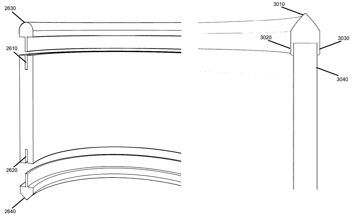
Provided are interchangeable bearing edge rings for drum shells assembled with traditional lug holders. Different bearing edge rings can be inserted in between the drum shell and the drumhead to change the sound of the drum during play. Some embodiments provide a modified drum shell with top and bottom rims that have a groove. Bearing edge rings with complimentary slits can be inset in the grooves in order to change the drum bearing edge and sound as desired. Alternatively, the bearing edge rings can have support extensions instead of the slits for coupling to unmodified drum shells. The support extensions extend downwards from either side of the ring and are separated by a distance equal to the width of the drum shell rim. The support extensions straddle the drum shell rim to retain the position of bearing edge ring over the drum shell rim.
Description
CLAIM OF BENEFIT TO RELATED APPLICATIONS[0001]This application is a continuation-in-part of the U.S. non-provisional application Ser. No. 14 / 536,606, entitled “Drum Mounting and Tuning System Providing Unhindered and Isolated Resonance”, filed Nov. 8, 2014 which is a continuation of the U.S. non-provisional application Ser. No. 14 / 092,400, entitled “Drum Mounting and Tuning System Providing Unhindered and Isolated Resonance”, filed Nov. 27, 2013, now U.S. Pat. No. 8,884,144, which is a continuation of the U.S. non-provisional application Ser. No. 13 / 857,924, entitled “Drum Mounting and Tuning System Providing Unhindered and Isolated Resonance”, filed Apr. 5, 2013, now U.S. Pat. No. 8,629,340. The contents of application Ser. Nos. 14 / 536,606, 14 / 092,400 and 13 / 857,924 are hereby incorporated by reference.TECHNICAL FIELD[0002]The present invention pertains to musical instrument structure and design and, more specifically, to drum structure and design.BACKGROUND[0003]Artistic expressio...
Claims
Application Information
Patent Timeline
Application Date:The date an application was filed.
Publication Date:The date a patent or application was officially published.
First Publication Date:The earliest publication date of a patent with the same application number.
Issue Date:Publication date of the patent grant document.
PCT Entry Date:The Entry date of PCT National Phase.
Estimated Expiry Date:The statutory expiry date of a patent right according to the Patent Law, and it is the longest term of protection that the patent right can achieve without the termination of the patent right due to other reasons(Term extension factor has been taken into account ).
Invalid Date:Actual expiry date is based on effective date or publication date of legal transaction data of invalid patent.