Witness enabled fasteners and related systems and methods

a technology of fasteners and enablers, applied in the field of fasteners, can solve the problems of further damage to the shaft and the second object, and/or the one or more other objects clamped there between

Active Publication Date: 2017-06-13
THE BOEING CO
View PDF11 Cites 18 Cited by
  • Summary
  • Abstract
  • Description
  • Claims
  • Application Information

AI Technical Summary

Benefits of technology

[0013]The present disclosure provides various apparatuses, systems, and methods associated with indicating stress, such as torque or other forces, on a fastener. In some embodiments, an apparatus, system, and / or method may enable monitoring and / or testing of torque (or other force) levels on a fastener via reception of a photo-luminescent signal from a sensor included in the fastener.

Problems solved by technology

Whereas if the bolt is over-tightened, then the shaft, the second object, and / or the one or more other objects clamped there between may become damaged.
Similarly, improperly seating the bolt in the hole may damage both the shaft and the second object.
However, various problems are associated with such devices.
Further, when using a torque wrench to check a previously tightened fastener, the torque wrench is generally incapable of determining whether the fastener has been torqued past the predetermined level without increasing the torque setting, which if so increased, would likely cause further damage.
Moreover, testing a fastener with a torque wrench generally requires mechanical engagement of the torque wrench with the fastener, resulting in significant torque testing times.

Method used


Image

  • Witness enabled fasteners and related systems and methods
  • Witness enabled fasteners and related systems and methods
  • Witness enabled fasteners and related systems and methods

Examples


example 1

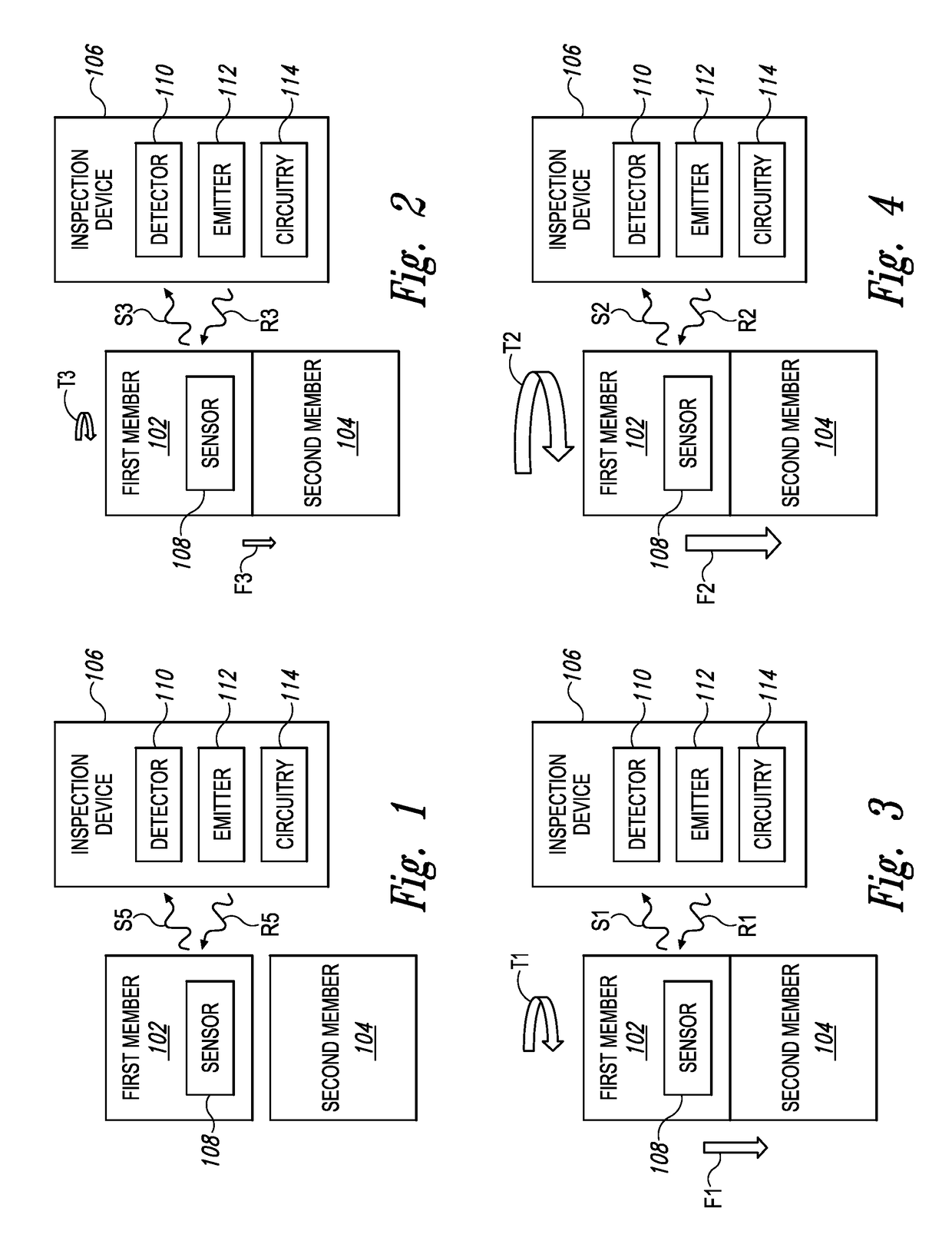
[0030]This example describes an illustrative system 100 including a first member 102, a second member 104, and an inspection device 106; see FIGS. 1-4.

[0031]First member 102 may be configured for forceful engagement with second member 104. For example, first member 102 may include a bolt (e.g., as shown in FIGS. 5-7), a washer (e.g., as shown in FIGS. 8 and 9), a nut, a lock-nut (e.g., a nylon lock nut, or ny-lock), a base with a threaded aperture for receiving a shaft, a clamp, a rivet, a clip, and / or any other suitable fastening member configured for forceful engagement with another member. For example, if first member 102 includes a bolt, then second member 104 may include an aperture having threads with which a threaded shaft of the bolt may be forcefully engaged. Similarly, if first member 102 includes a washer, then second member 104 may include a bolt, a nut, and / or another base-type fastening member against which the washer may be forcefully engaged.

[0032]As shown in FIGS. 1...

example 2

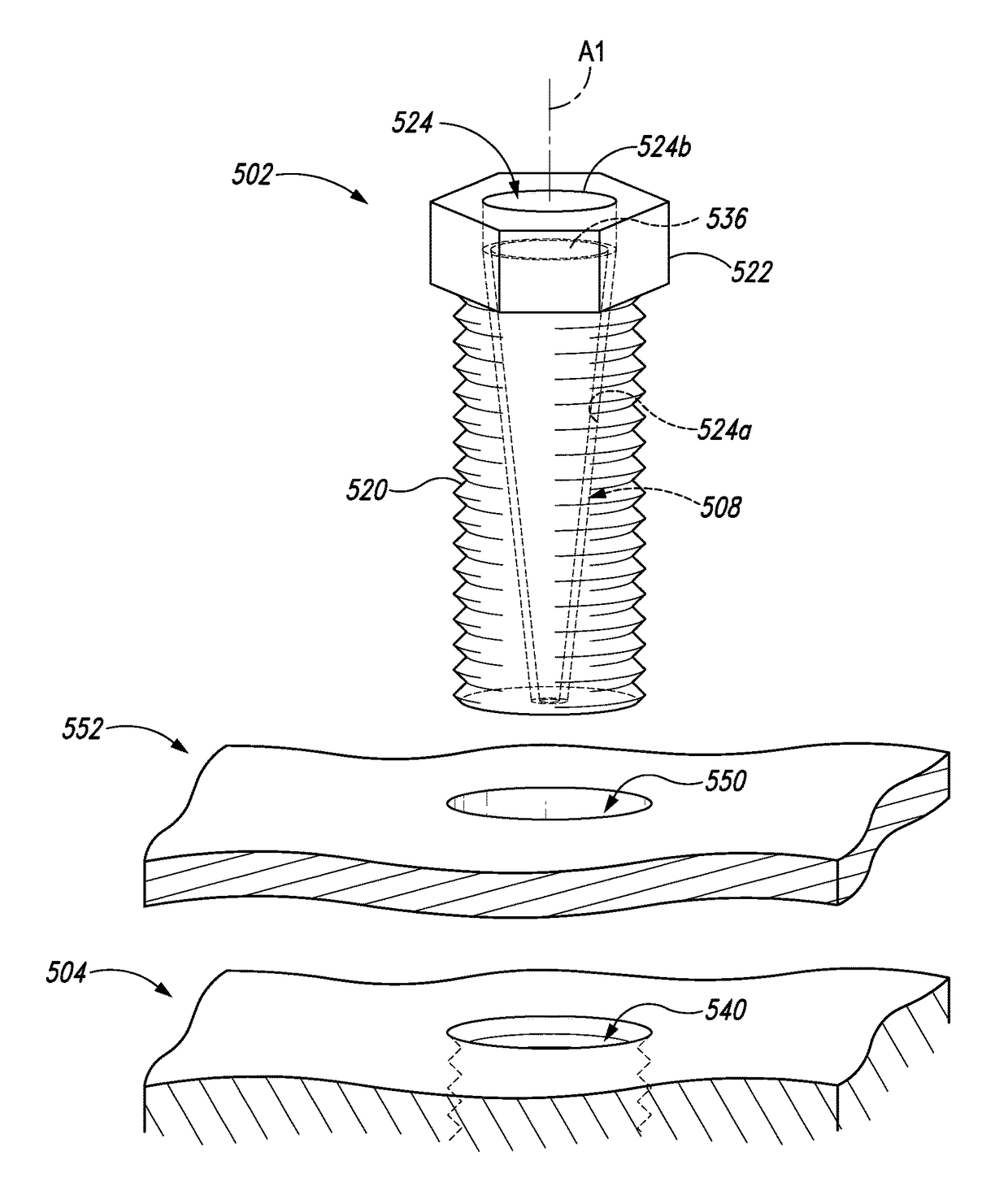
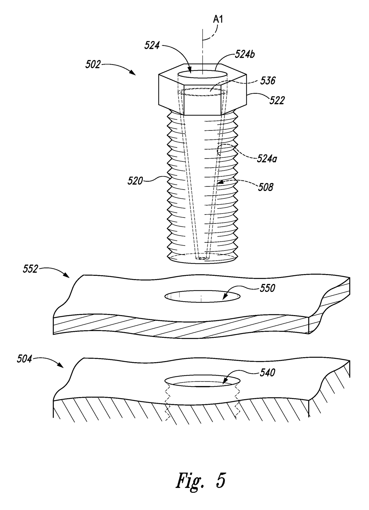
[0059]This example describes a system 500 including a first member 502, a second member 504, and a tool 506; see FIGS. 5-7.

[0060]System 500 is an embodiment of system 100. For example, first member 502 may be configured for forceful engagement with second member 504, and may include a sensor 508 configured to emit one or more photo-luminescent signals indicative of the forceful engagement of first member 502 with second member 504. Further, tool 506 may include an inspection device 509 (see FIG. 6), which may comprise a detector 510, an emitter 512, and circuitry 514. Detector 510 may be configured to system 500 in a manner similar to detector 110 in system 100. Similarly, emitter 512 and circuitry 514 may be configured to system 500 in a manner similar to emitter 112 and circuitry 114 in system 100, respectively. For example, detector 510 may be configured to receive the one or more photo-luminescent signals, which may be emitted from sensor 508 in response to absorption of radiati...

example 3

[0083]This example describes a system 800 including a first member 802 (e.g., a washer), a second member 804 (e.g., a bolt), a third member 806, and a tool 808; see FIGS. 5-7.

[0084]System 800 is an embodiment of system 100. For example, first member 802 may be configured for forceful engagement with second member 804 (and third member 806), and may include a sensor 810 configured to emit one or more photo-luminescent signals indicative of the forceful engagement of first member 802 with second member 804 (e.g., a forceful engagement of first member 802 between members 804, 806). Further, tool 808 may include an inspection device 812 (see FIG. 9), which may comprise a detector 814, an emitter 816, and circuitry 818. Detector 814 may be configured to system 800 in a manner similar to detector 110 in system 100 and / or in a manner similar to detector 510 in system 500. Similarly, emitter 816 and circuitry 818 may be configured to system 800 in a manner similar to emitter 112 and circuit...


PUM

PropertyMeasurementUnit
torqueaaaaaaaaaa
forceaaaaaaaaaa
torqueaaaaaaaaaa

Abstract

A fastening device may include a first member configured for forceful engagement with a second member. The first member may include a sensor configured to emit at least a first photo-luminescent signal to a detector when at least a predetermined first torque level is applied to the first member when the first and second members are engaged.

Description

FIELD[0001]This disclosure relates to fasteners. More specifically, the disclosed embodiments relate to systems and methods for indicating a level of force on a fastener.INTRODUCTION[0002]Generally, a fastener is a hardware device that mechanically joins two or more objects, sometimes temporarily. For example, a bolt is one type of fastener, which in some cases has a threaded shaft and a head. The bolt and a second object, such as a nut or a base, can be mechanically joined by threading the threaded shaft into a complimentarily threaded hole in the second object. Typically, one or more other objects are disposed between the head and the second object. In such cases, mechanically joining the bolt and the second object may clamp the one or more other objects between the head and the second object.[0003]In some situations, it may be desirable to know when a fastener is under-tightened, over-tightened, and / or improperly seated. For example, if a bolt is under-tightened into the second o...

Claims


Application Information

Patent Timeline
Patent Type & Authority Patents(United States)
IPC IPC(8): F16B31/02G01L1/24G01L5/24G01L5/00G01N21/64
CPCF16B31/02G01L1/24G01L5/0004G01L5/24G01L5/243G01N2021/6439F16B31/028
Inventor BERNHARDT, ROGER D.
Owner THE BOEING CO
Why Eureka
Try Eureka