Back support assembly for the back of a chair

a back support and back support technology, applied in the field of back support assemblies, can solve the problems of user's back posture suffering, user's lower back pain and discomfort, and the back of the chair does not offer back support for the user,

Active Publication Date: 2017-06-27
GROVE JAMES E
View PDF4 Cites 11 Cited by
  • Summary
  • Abstract
  • Description
  • Claims
  • Application Information

AI Technical Summary

Benefits of technology

[0010]When the seat and back of the chair tilt forwards and the user sits erect in the chair, the rollers carried by the upstanding and vertically stationary force generating strap will be positioned near the bottom of the roller pad that is affixed to the backing at the rear of the chair back. At the same time, the rollers of the force generating strap press against and apply a pushing force to the rotatable back support pushing arm. The back support pushing arm is thusly rotated in a counter-clockwise direction at the hinge thereof towards a first position during which the rollers carried by the pushing arm ride downwardly along the front of the chair back and thereby cause the curved back support to rotate in a first direction away from the backing at the rear of the chair back so as to protrude outwardly from the front of the chair back and towards the back of the user.

Problems solved by technology

A common problem with such conventional home and office chairs occurs when the chair rocks forward and the user tries to hold his back erect and close to the work surface.
Therefore, the chair back offers no support for the user's back throughout those times when the user is working.
Consequently, the user's back posture may suffer and, especially during long periods of work, the user may experience lower back pain and discomfort.

Method used


Image

  • Back support assembly for the back of a chair
  • Back support assembly for the back of a chair
  • Back support assembly for the back of a chair

Examples


Embodiment Construction

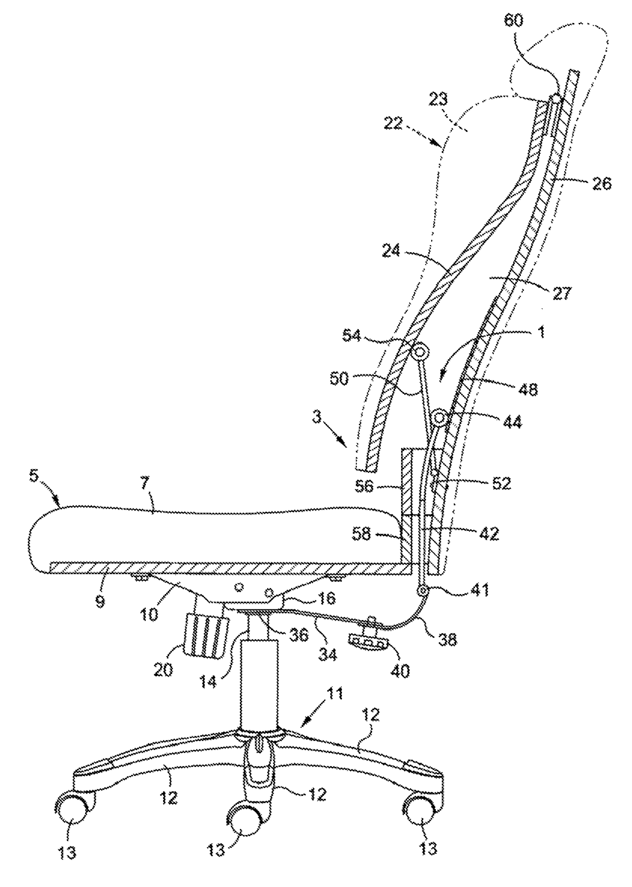
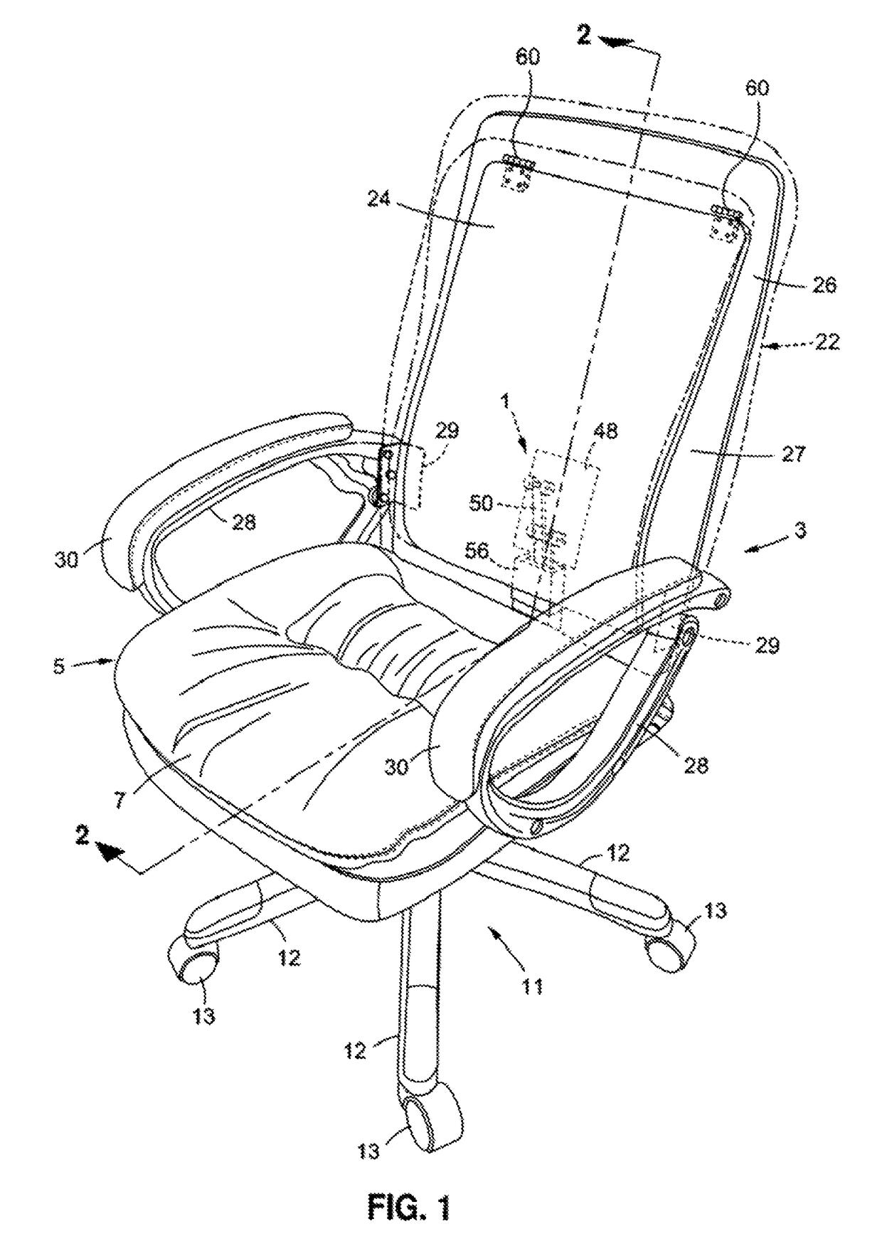
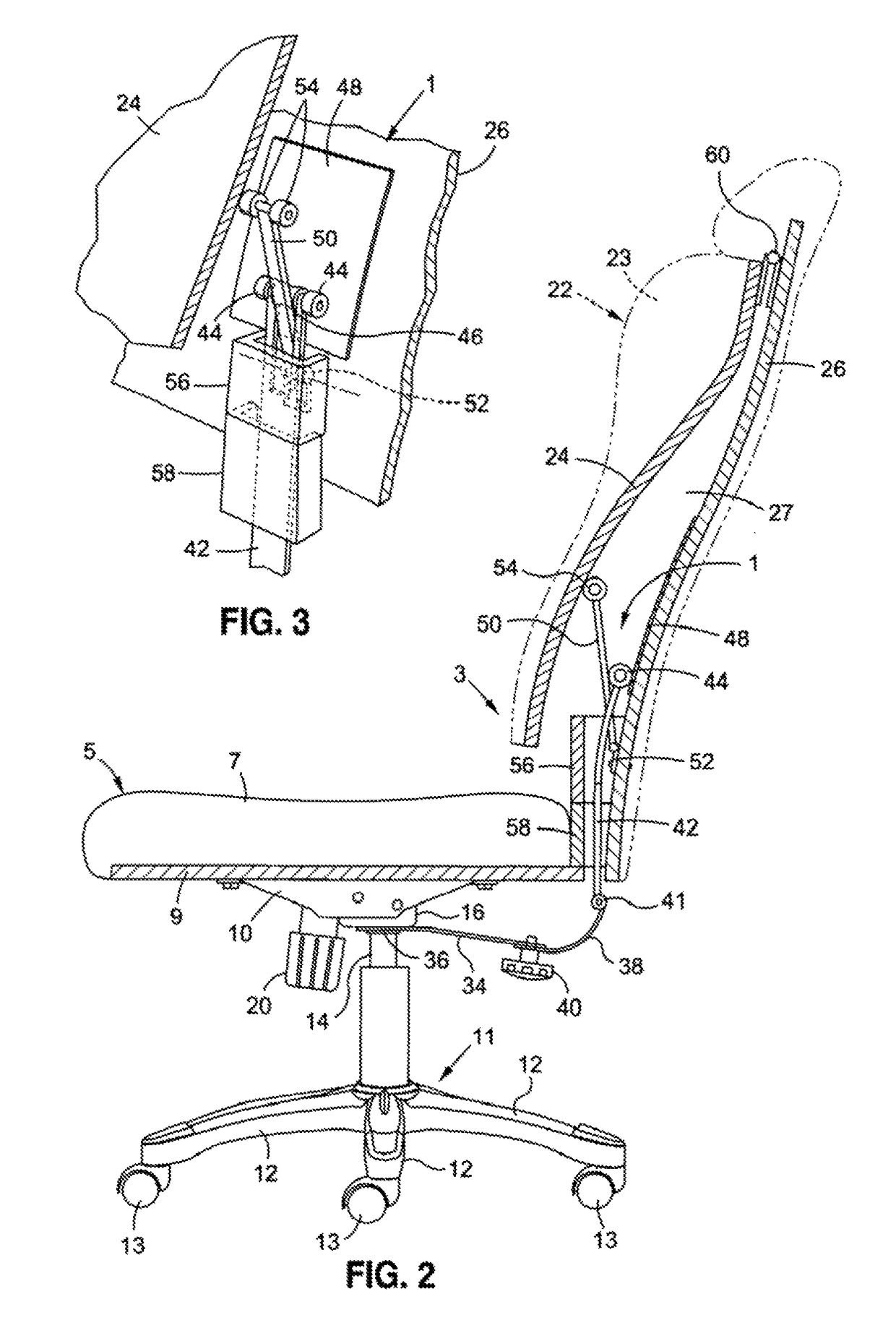
[0017]Referring concurrently to FIGS. 1-4 of the drawings, a back support assembly 1 is shown and disclosed for use at the back of a chair 3. The chair 3 is one that rocks back and forth and is of the kind that would be commonly found in a home or office to provide a comfortable seat for one working at a desk, a table or a similar work surface. However, the specific use of the chair 3 is not to be regarded as a limitation of this invention.

[0018]The chair 3 includes a seat 5 to support the weight of a user. The seat 5 has a cushion surface 7 secured atop a solid (e.g., plywood) seat support 9. A seat tilt control bracket 10 is affixed to and projects below the seat support 9. The chair seat 5 is held above the ground by a base 11 having a set of outstretched legs 12 to which respective rollers 13 are attached to permit the chair to be moved from place to place. A gas cylinder 14 extends between the base 10 and a gas cylinder receiver 16 that lies below the seat 5 and is affixed to t...


PUM


Abstract

A back support assembly for the back of a chair that rocks back and forth. The back of the chair includes a front that is spaced from and pivotally coupled to a rear. The front of the chair back is rotatable towards and away from the back of a user. A back support pushing arm within the back of the chair is pivotally coupled to the rear of the chair back and rotatable between a first position at which to apply a pushing force against the front of the chair back when the chair rocks forwards and a second position when the user leans back, the chair rocks backwards, and the front of the chair rotates towards the rear. A force generating strap within the chair back contacts and urges the back support pushing arm to rotate to the first position lying against the front of the chair back.

Description

BACKGROUND OF THE INVENTION[0001]1. Field of the Invention[0002]This invention relates to a back support assembly that is located inside the back of a chair of the kind that rocks back and forth and is typically found in a home or office adjacent a work surface. The back support assembly includes a curved back support that is rotatable in a first direction when the chair rocks forwards at which to protrude outwardly from the chair back towards the back of a user and in an opposite direction inwardly of the chair back when the chair rocks backwards at which to allow the user to lean completely back and recline against the chair back.[0003]2. Background Art[0004]A wide variety of chairs have been used in a home or an office to enable a user to be seated adjacent a work surface such as a desk. In this case, the user can access a computer, a book, a writing pad, etc. which lays upon the work surface so that the user can work while seated. Some chairs are adapted to rock back and forth i...

Claims


Application Information

Patent Timeline
Patent Type & Authority Patents(United States)
IPC IPC(8): A47C7/56A47C7/44
CPCA47C7/566A47C7/445A47C1/03255A47C1/033A47C7/462A47C4/46
Inventor GROVE, JAMES E.
Owner GROVE JAMES E
Why Eureka
Try Eureka