Eureka AIR delivers breakthrough ideas for toughest innovation challenges, trusted by R&D personnel around the world.

Working vehicle

a technology for working vehicles and trucks, applied in mechanical machines/dredgers, soil shifting machines/dredgers, construction, etc., can solve the problems of unstable working vehicles, vehicle overturning forward, and vehicle receiving the influence of bucket cargo weight, etc., to achieve excellent vehicle stability, excellent stability and operability, and compact appearance design

Active Publication Date: 2017-07-04
TAKEUCHI SEISAKUSHOKK
View PDF7 Cites 0 Cited by
  • Summary
  • Abstract
  • Description
  • Claims
  • Application Information

AI Technical Summary

Benefits of technology

[0016]According to the working vehicle relating to the present invention configured as described above, by employing what is called the vertical type supporting mechanism, when the arm has been oscillated upward from a low moving position, the working vehicle can be configured to be able to move the arm front end upward while smoothly moving the arm front end forward to the middle, and thereafter, move the arm front end upward smoothly and substantially vertically. Therefore, by configuring the working vehicle to move the arm front end upward while smoothly moving the arm front end forward to the middle, and thereafter, move the arm front end upward smoothly and substantially vertically, it is possible to obtain the working vehicle with excellent stability and operability of the vehicle at the time of vertically oscillating the arm. Further, each control link is extended substantially horizontally at the arm lowest moving position, and the arm cylinder and the lift link can be arranged in compact so as to be extended horizontally and vertically upward by bringing the arm cylinder and the lift link close to each other. As a result, a compact appearance design can be obtained.
[0017]Further, the working vehicle relating to the present invention has a configuration in which, at the arm lowest moving position, the control link is approximately horizontally extended backward, that is, a configuration in which the pivotal connection point D is located in approximately the same height as that of the pivotal connection point A. Therefore, in the configuration in which the control link is arranged to be extended upward toward the back from the pivotal connection point A, for example, it is possible to lower a position of a mechanical instantaneous center of the arm (also simply referred to as an “instantaneous center”, and a center point when it can be regarded that the arm is performing a rotation movement around a certain point at a certain moment) in the state in which the arm is located near the lowest moving position. A moving speed of the arm front end is defined as a component in a direction orthogonal with a line component that connects an instantaneous center of the arm and the arm front end. Therefore, by lowering the instantaneous center position of the arm as described above, the arm front end can be moved substantially vertically, by suppressing forward movement of the arm front end when oscillating the arm near the lowest moving position, by minimizing a horizontal directional component of the moving speed of the arm front end. Consequently, the working vehicle with excellent vehicle stability can be obtained.

Problems solved by technology

Therefore, particularly when the arm is vertically oscillated in the state in which a heavy object is loaded in the bucket, there is a risk that the vehicle overturns forward.
However, as in the working vehicle in U.S. Pat. No. 6,474,933, if the arm front end is located at a front position when the arm is oscillated to a high moving position, although the distance over which the own vehicle moves for loading onto the carrying vehicle becomes short, the vehicle receives the influence of the weight of the bucket cargo and becomes unstable at the time of lifting the arm.
This has a problem in that the weight center of the vehicle changes longitudinally following the oscillation of the arm, and the working vehicle cannot be easily operated (has poor operability).

Method used


Image

  • Working vehicle
  • Working vehicle
  • Working vehicle

Examples


Embodiment Construction

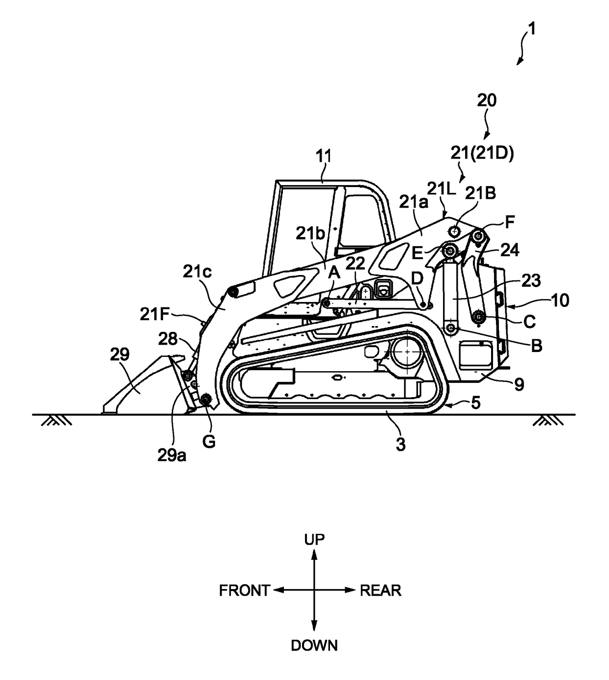
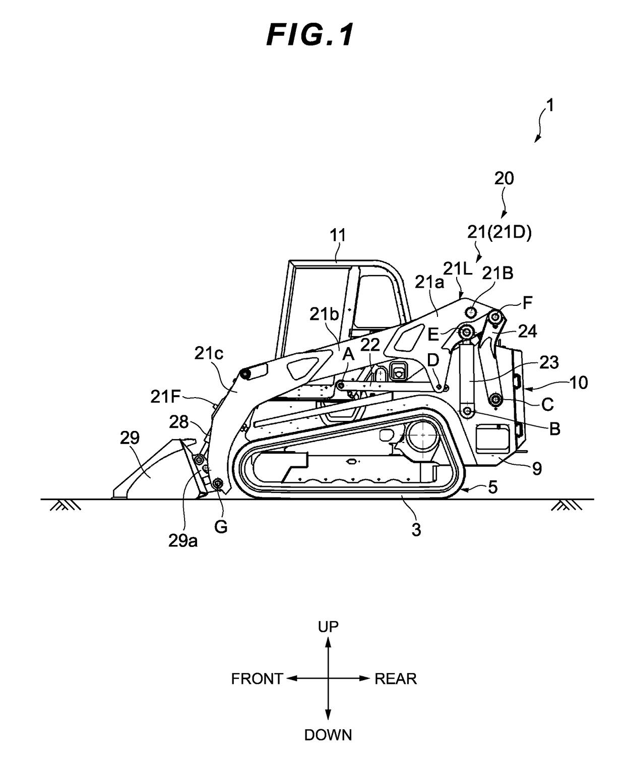
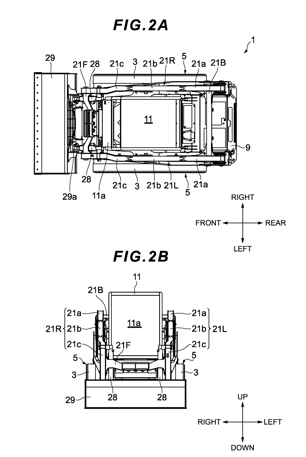
[0028]An embodiment of the present invention will be described below with reference to the drawings. In the present embodiment, there will be described an example of application of the present invention to a crawler type skid steering loader (hereinafter, referred to as a crawler loader 1) having a bucket mounted on the front end of the arm. First, a total configuration of the crawler loader 1 will be described with reference to FIGS. 1 to 3. In the following, for convenience of the description, front and rear, left and right, and above and below will be defined using arrow directions attached to the drawings.

[0029]As illustrated in FIG. 1, the crawler loader 1 is configured to include: a pair of left and right running devices 5 configured to have an endless belt 3; a main body frame 9 provided with the running devices 5 on the left and right sides thereof; a loader device 20 installed on the main body frame 9; and an operator cabin 11 provided on a center upper part of the main bod...


PUM


Abstract

In a state in which an arm 21 is oscillated to a lowest position, each control link 22 is arranged to be horizontally extended backward where the control link 22 is pivotally connected to a point A, and is pivotally connected to the arm 21 at a point D. An arm cylinder 23 is arranged to be vertically extended upward where the arm cylinder 23 is pivotally connected to a point B, and is pivotally connected to the arm 21 at a point E. The lift link 24 is arranged to be vertically extended upward where the lift link 24 is pivotally connected to a point C, and is pivotally connected to the arm 21 at a point F. The points E and F are located above the point D.

Description

RELATED APPLICATIONS[0001]This invention claims the benefit of Japanese Patent Application No. 2014-152554 which is hereby incorporated by reference.TECHNICAL FIELD[0002]The present invention relates to a working vehicle in which an arm is provided on a runnable vehicle main body so as to freely oscillate vertically, and which performs a work by vertically moving an attachment (a working device) detachably installed on an arm front end by vertically oscillating the arm.TECHNICAL BACKGROUND[0003]As an example of such a working vehicle, there has been known a skid steering loader in which running devices configured by tires or crawlers are provided on both left and right sides of the vehicle main body such that the traveling direction of the working vehicle is changed by making working speeds of the left and right running devices different. An arm supporting mechanism that is provided in the skid steering loader and vertically oscillates the arm is broadly classified into: a radial ty...

Claims


Application Information

Patent Timeline
Patent Type & Authority Patents(United States)
IPC IPC(8): E02F3/42E02F3/34
CPCE02F3/422E02F3/34E02F3/3414
Inventor ITO, SHUSAKU
Owner TAKEUCHI SEISAKUSHOKK
Why Eureka
Eureka Blog
Learn More