
Fastening bolt for use in concrete

a technology for fastening bolts and concrete, applied in the direction of fastening means, screws, threaded fasteners, etc., can solve the problems of inability to break the concrete wall, time and effort required to drill, and the conventional structure still has problems, etc., to achieve convenient mechanical properties, resist the effect of drilling resistance and quick drilling operation

Active Publication Date: 2017-07-04
HOME SEN
View PDF11 Cites 4 Cited by
  • Summary
  • Abstract
  • Description
  • Claims
  • Application Information

AI Technical Summary

Benefits of technology

The bolt achieves rapid drilling and firm engagement with the concrete, reducing torque resistance and preventing misalignment, thereby enhancing the fastening effect and mechanical properties such as anti-torque and tensile strength.

Problems solved by technology

This conventional structure still has problems.
A user may impart more rotating force to overcome the resistance, but it takes time and effort to drill.
Thus, the thread structure cannot break the concrete wall 2 effectively and cannot drill vertically.
These problems render wall pieces broken by the drilling action unable to travel within the hole 21 easily, so the threads 14 cannot engage the concrete wall 2 firmly after the drilling action.

Method used


Image

  • Fastening bolt for use in concrete
  • Fastening bolt for use in concrete
  • Fastening bolt for use in concrete

Examples


Embodiment Construction

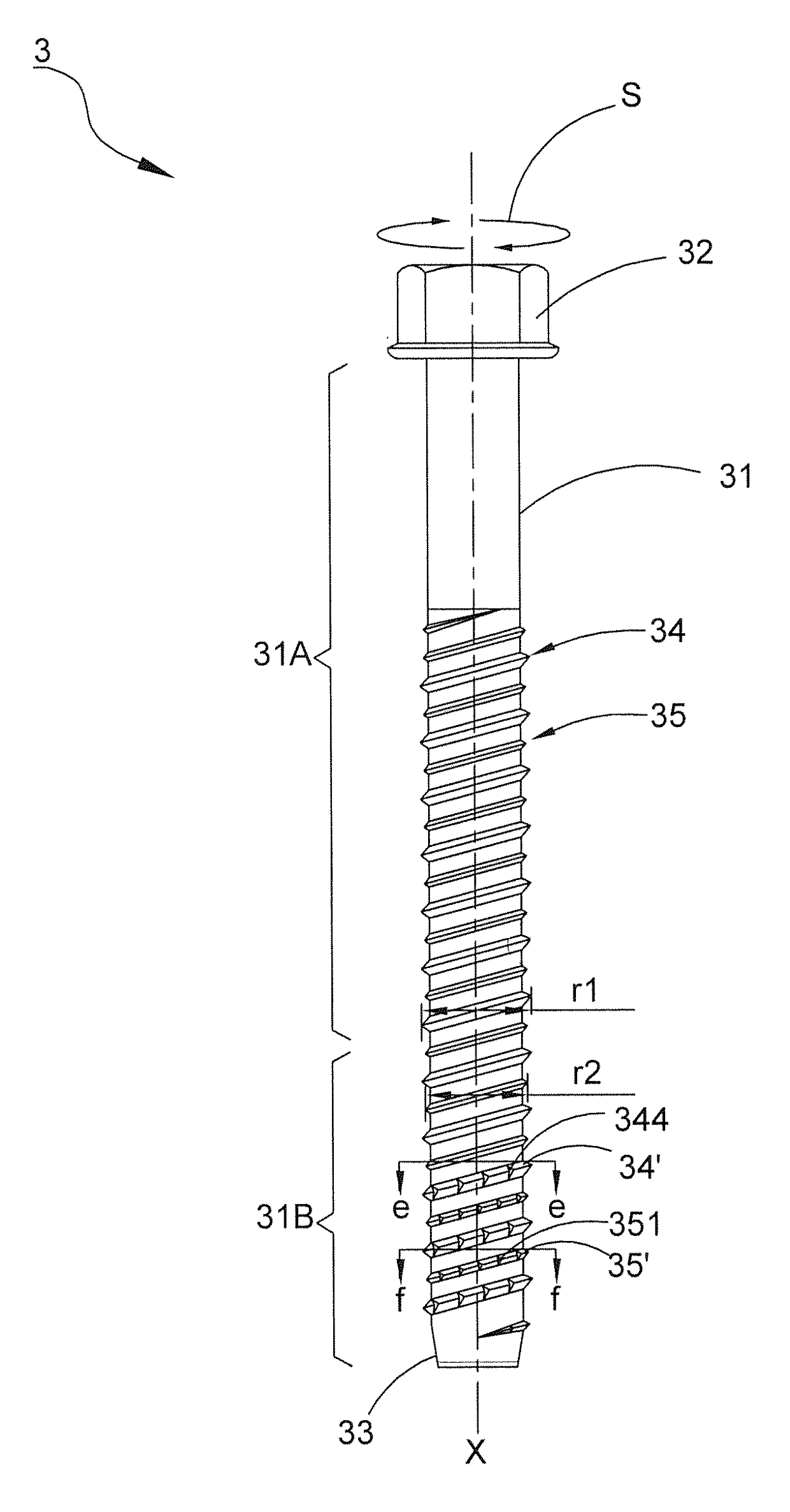
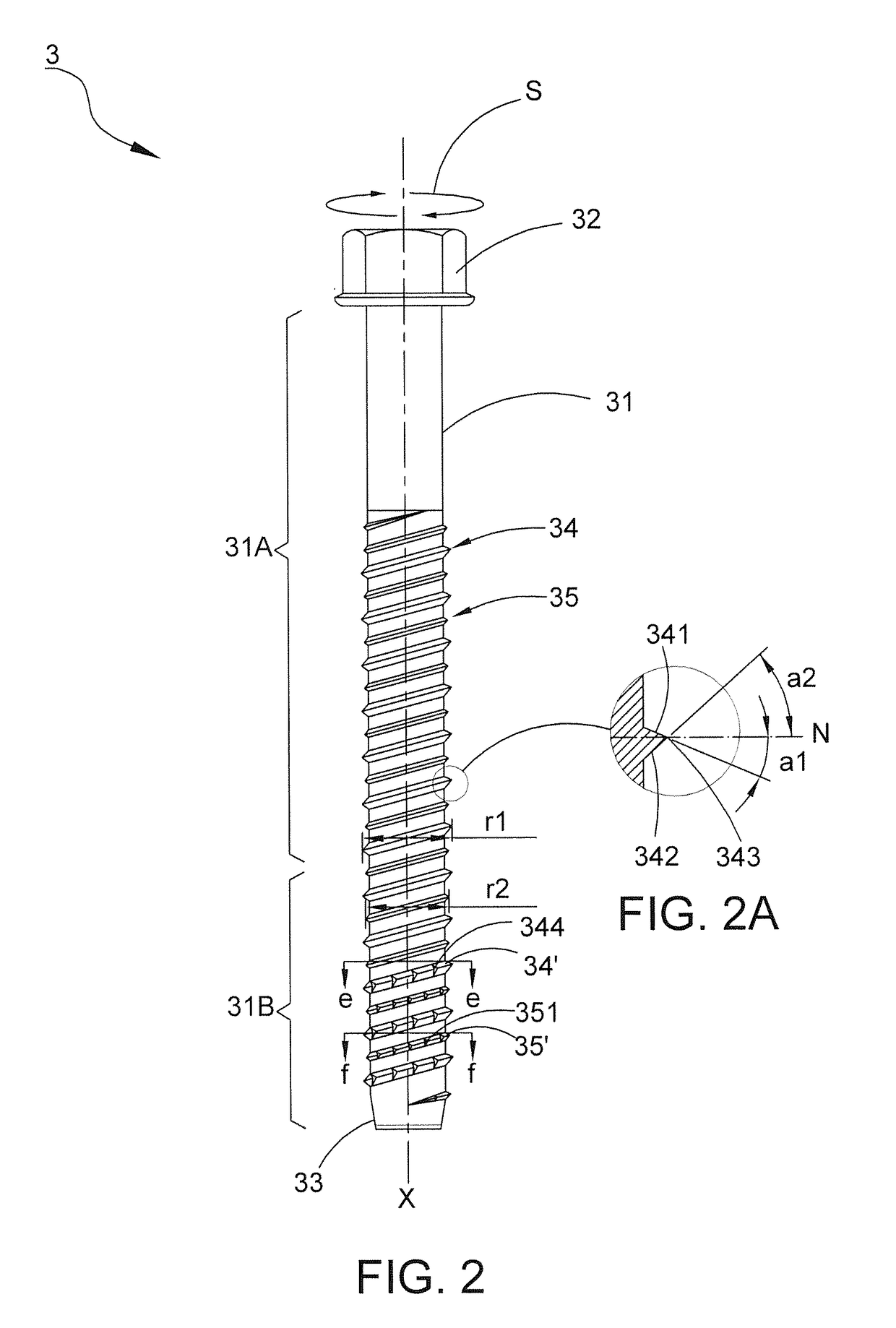
[0017]Referring to FIG. 2, a fastening bolt 3 for use in concrete of the first preferred embodiment includes a shaft 31 defining a central axis X, a head 32 disposed on a first end of the shaft 31, a drilling portion 33 formed on a second end of the shaft 31 opposite to the first end, a plurality of first threads 34, 34′ spirally disposed on the shaft 31 and extending from the drilling portion 33 toward the head 32, and a plurality of second threads 35,35′ spirally disposed between the first threads 34, 34′. Also referring to FIG. 2A, each of the first threads 34, 34′ has a trailing surface 341 facing the head 32 and a leading surface 342 facing the drilling portion 33. The leading surface 342 and the trailing surface 341 converge on a thread ridge 343. A line N perpendicular to the central axis X of the shaft 31 is defined to pass the thread ridge 343. The leading surface 342 and the trailing surface 341 are respectively orientated at respective angles. In other words, the leading ...


PUM


Abstract

A fastening bolt includes a shaft defining a central axis, a head, a drilling portion, and first threads alternating with second threads. The first threads and the second threads have different outer diameters. Each first thread has a trailing surface facing the head and inclined to a line perpendicular to the central axis by a trailing angle and a leading surface facing the drilling portion and inclined to the line by a leading angle. The trailing angle is smaller than the leading angle to build an asymmetrical form. Some threads near the drilling portion form respective cutting grooves and recesses thereon. Each cutting groove is formed by walls with different lengths and opened at an angle which does not exceed 90 degrees. The bolt breaks the workpiece quickly by the cutting grooves and recesses. The asymmetrical first threads help enter the workpiece quickly and attain a firm engagement therewith.

Description

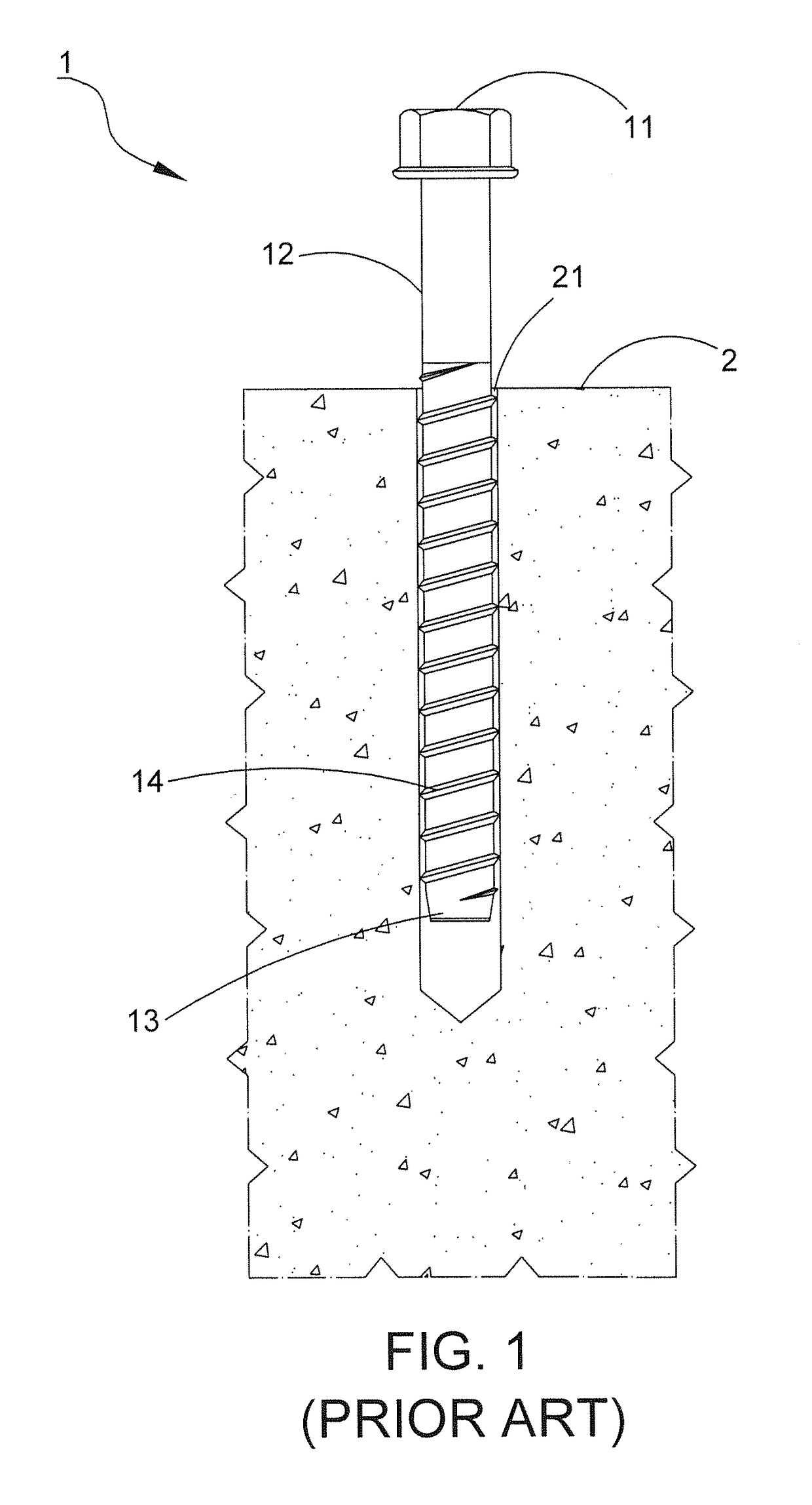
BACKGROUND OF THE INVENTION[0001]1. Field of the Invention[0002]This invention relates to a fastener and relates particularly to a fastening bolt for use in the concrete.[0003]2. Description of the Related Art[0004]Referring to FIG. 1, a conventional concrete bolt 1 comprises a head 11, a shaft 12 connected to the head 11, a drilling portion 13 disposed at a distal end of the shaft 12 and a plurality of threads 14 spirally disposed on the shaft 12. A screwing operation of the concrete bolt 1 is executed by using an electric drill (not shown) to drill a pilot hole 21 in a concrete wall 2 in advance and then inserting the concrete bolt 1 into the hole 21 for engaging the concrete wall 2. This conventional structure still has problems. For example, the concrete bolt 1 usually has symmetrical threads 14. In other words, an upper flank surface and a lower flank surface of each thread 14 have the same inclined angle relative to a normal line passing an edge where the two surfaces meet, so...

Claims


Application Information

Patent Timeline
Patent Type & Authority Patents(United States)
IPC IPC(8): F16B25/02F16B25/00F16B25/10
CPCF16B25/0026F16B25/0052F16B25/0068F16B25/10F16B25/0047
Inventor WU, CHENG-YEN
Owner HOME SEN
Learn More