Garment steamer and method for the same

a technology for garments and steamers, applied in carpet cleaners, floor cleaners, textiles and paper, etc., can solve the problems of easy strained and exhausted parts of the arm carrying even a small water tank

Inactive Publication Date: 2017-08-29
KONINKLJIJKE PHILIPS NV
View PDF25 Cites 4 Cited by
  • Summary
  • Abstract
  • Description
  • Claims
  • Application Information

AI Technical Summary

Benefits of technology

[0008]More in particular, it is an object of the present invention to provide for a garment steamer that is more portable than know floor model steamers, that provides for more of autonomy than known hand-held steamers, and that offers a generally improved manageability / maneuverability of the steam head.
[0024]The steam guard serves to protect a user's hand gripping the elongate handle section of the steam head's housing from direct contact with the hot steam released through the at least one steam nozzle. It may preferably be formed as a generally sheet- or plate-like collar or flange that extends away from, and at least partially around the nozzle head. In a preferred embodiment, the steam guard may extend away from the nozzle head in a direction having a positive component in a direction extending from the first end of the elongate handle section to the second end thereof. This latter configuration may be particularly advantageous in case the at least one steam nozzle is configured to release steam in a direction that extends at a non-zero angle relative to the longitudinal axis of the elongate handle.

Problems solved by technology

This is in particular true over longer time periods, during which a partially stretched arm carrying even a small water tank could be strained and exhausted easily.

Method used


Image

  • Garment steamer and method for the same
  • Garment steamer and method for the same
  • Garment steamer and method for the same

Examples


Embodiment Construction

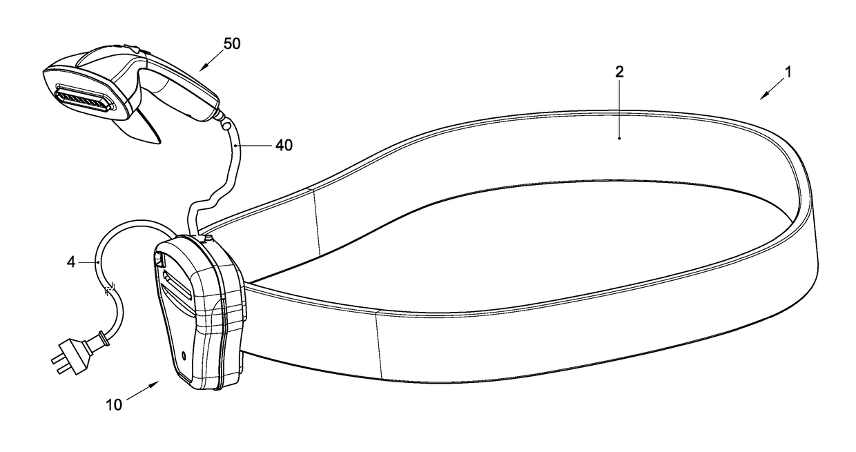
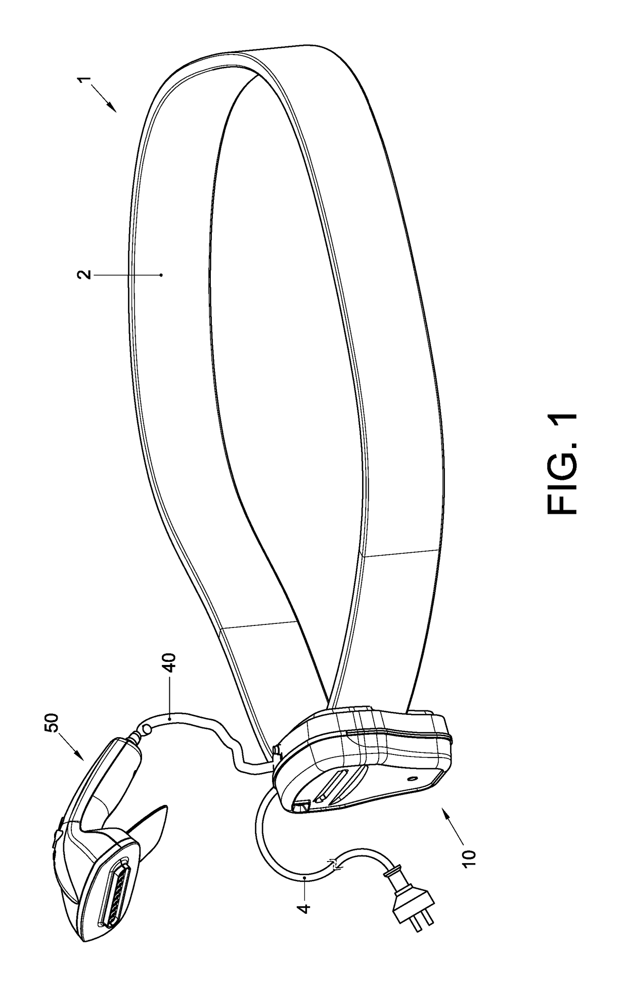
[0035]FIG. 1 is a schematic perspective view of an exemplary embodiment of a garment steamer 1 according to the present invention. The garment steamer includes a base body 10, a steam head 50 that is connected thereto via a flexible connection cord 40. The garment steamer also includes a power cord 4 provided with a plug, which cord is connected to the base body 10 for supplying the garment steamer 1 with electrical power from the mains.

[0036]In the depicted embodiment, the base body 10 is provided on a belt 2, e.g. a waist belt, that enables a user to strap the base body 10 to his body, e.g. around his waist. The base body 10 is relatively lightweight, so bearing it is in itself unlikely to present a physical burden to a user. However, holding the base body 10 manually would necessarily take up one of a user's hands. The waist belt 2 overcomes the need to hold base body 10 manually during use, thus freeing that hand, which may then be used for, for example, rearranging a garment be...


PUM


Abstract

A garment steamer (1) comprising a base body (10) accommodating a liquid water tank (26); a liquid water pump (32), having a water inlet (32a) and a water outlet (32b), wherein the water inlet (32a) is fluidly connected to the liquid water tank (26). The garment steamer also comprises a steam head (50) that is moveable with respect to the base body (10) and that accommodates a steam chamber (70), having a liquid water inlet and a steam outlet, wherein said steam outlet includes at least one steam nozzle (76); a heating element (72) that is provided in or adjacent said steam chamber (70), and configured to evaporate liquid water passing through said steam chamber. A liquid water tube (38b, 38c) fluidly interconnects the water outlet (32b) of the water pump (32) and the liquid water inlet of the steam chamber (70) in the steam head (50).

Description

CROSS-REFERENCE TO PRIOR APPLICATIONS[0001]This application is the U.S. National Phase application under 35 U.S.C. §371 of International Application No. PCT / IB2012 / 055599, filed on Oct. 15, 2012, which claims the benefit of U.S. Provisional Patent Application No. 61 / 548,257, filed Oct. 18, 2011. These applications are hereby incorporated by reference herein.FIELD OF THE INVENTION[0002]The present invention relates to a portable garment steamer, and to a method for steaming a fabric using said garment steamer.BACKGROUND OF THE INVENTION[0003]To remove wrinkles from fabrics, in particular garments, one may turn to a variety of tools for assistance. Two popular tools for home use are the iron and the garment steamer. Although these devices have a generally similar purpose, they belong to distinct technical classes, each characterized by its own set of constructional features, method of use, performance level and suitability for taking care of certain materials.[0004]From a construction...

Claims


Application Information

Patent Timeline
Patent Type & Authority Patents(United States)
IPC IPC(8): A47L11/34D06F87/00D06F75/20D06F75/12D06F73/00A47L11/40
CPCD06F87/00A47L11/34A47L11/4086D06F73/00D06F75/12D06F75/20
Inventor DATE, MILIND VISHWASJIANG, YONGLEE, NICHOLAS JOHNPELGRIM, MAARTEN THEODOOR HENRIC
Owner KONINKLJIJKE PHILIPS NV
Why Eureka
Try Eureka