Jewelry ring

a technology for jewelry rings and rings, applied in the field of jewelry products, can solve the problem that the construction does not allow for the interchangeability of at least a portion of the jewelry ring

Active Publication Date: 2017-09-12
NAT CHAIN
View PDF2 Cites 31 Cited by
  • Summary
  • Abstract
  • Description
  • Claims
  • Application Information

AI Technical Summary

Problems solved by technology

However, the existing constructions do not allow for an interchangeability of at least a portion of the jewelry ring.

Method used


Image

  • Jewelry ring
  • Jewelry ring
  • Jewelry ring

Examples


Embodiment Construction

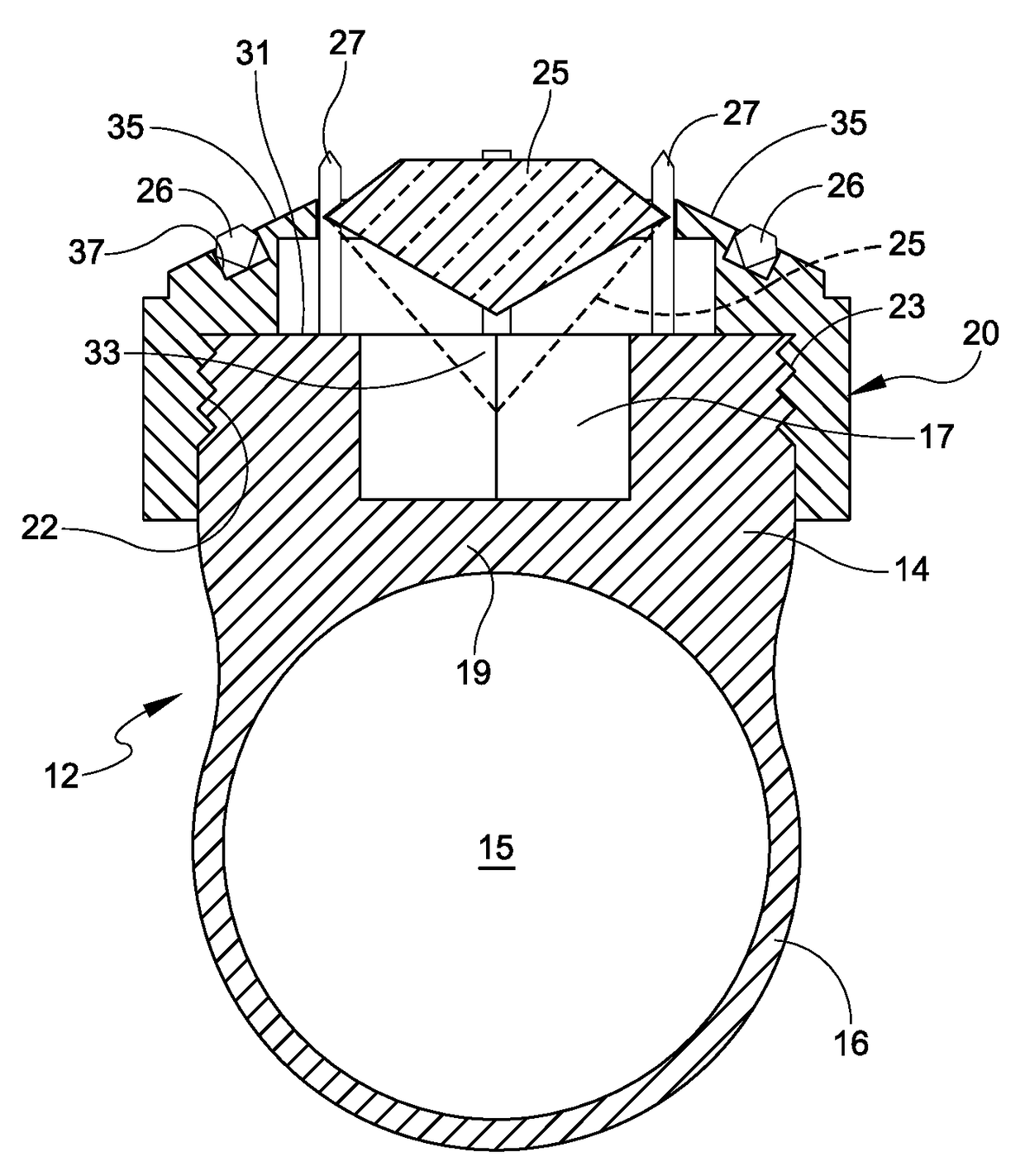
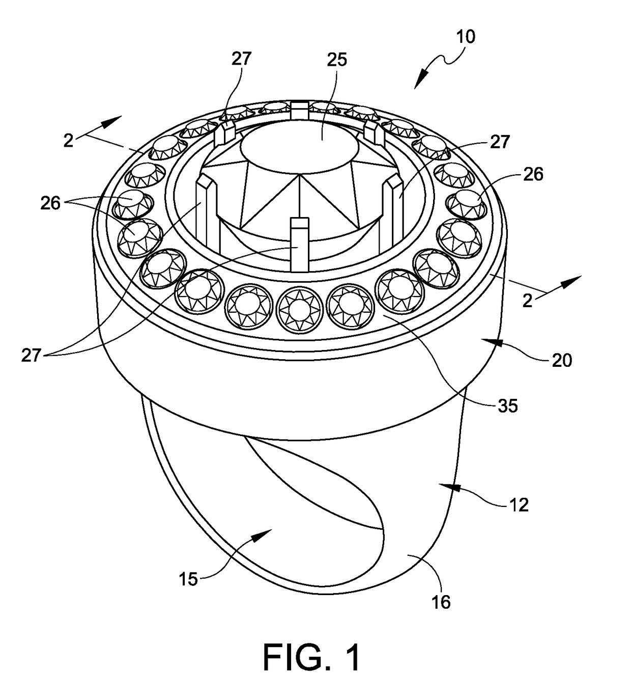
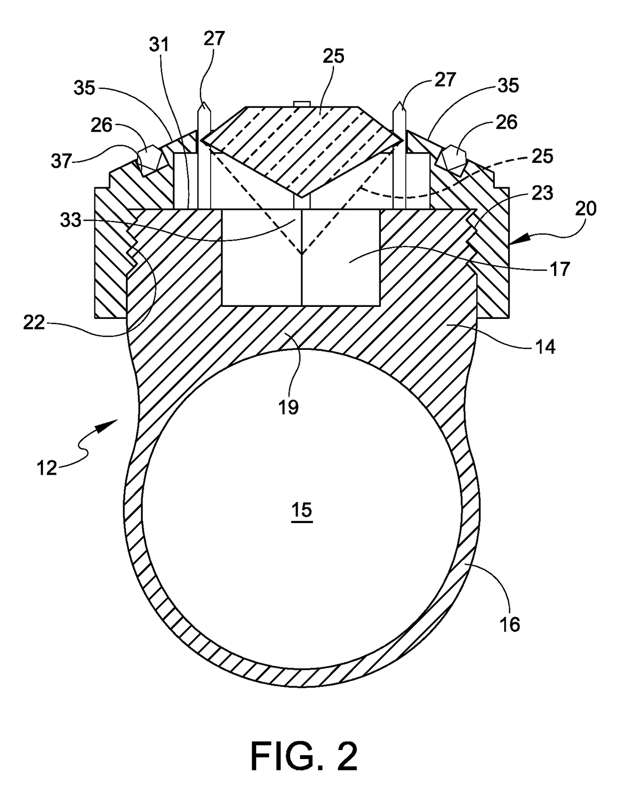
[0017]Reference is now made to a first embodiment of the present invention illustrated in FIGS. 1-4. This jewelry product is comprised of an annular member 12 having a receiving passage 15 that is meant to be engaged with the finger, or possibly the toe, of the user. The annular member 12 includes a circular or cylindrical top portion 14 as depicted in the cross-sectional view of FIG. 2. The circular or cylindrical top portion 14 is integrally formed with the base portion 16. The base portion 16 is the portion that is provided with the passage 15 for receiving the finger or toe or possibly a chain link or other filament type piece. The circular top portion 14 has a central aperture 17 that extends generally toward the passage 15 leaving a thin wall at 19 defined over the passage 15.

[0018]To provide for the interchangeability of the jewelry items, there is provided a circular mounting member 20 that is constructed and arranged for engagement over and with the circular or cylindrical ...


PUM


Abstract

A jewelry product for wearing on the finger includes an annular member with a receiving passage that is meant to be engaged with the finger. The annular member includes a circular top portion that is integral with a base portion, said base portion being provided with the passage for engagement with the finger, and the circular top portion having a central aperture extending in the direction of the passage, and a circular mounting member for engagement over and with the circular top portion of the annular member. Inter-engageable threads are disposed between the circular mounting member and the circular top portion so as to enable the circular mounting member to be secured with or removed from the circular top portion of the annular member.

Description

RELATED APPLICATIONS[0001]Priority for this application is hereby claimed under 35 U.S.C. §119(e) to commonly owned U.S. Provisional Patent Application Nos. 62 / 243,283 and 62 / 243,278 which were both filed on Oct. 19, 2015 and each of which is incorporated by reference herein in its entirety.FIELD OF THE INVENTION[0002]The present invention relates in general to a jewelry product in the form of a jewelry ring for wearing on the finger. More particularly, the present invention relates to an improvement in the jewelry ring to enable an interchange of different head constructions of the jewelry ring.BACKGROUND OF THE INVENTION[0003]There are a great number of different jewelry ring constructions that are available. However, the existing constructions do not allow for an interchangeability of at least a portion of the jewelry ring. This interchangeability, in accordance with the present invention, enables the ring structure to have different mounting pieces so as to display different typ...

Claims


Application Information

Patent Timeline
Patent Type & Authority Patents(United States)
IPC IPC(8): A44C9/00A44C17/02
CPCA44C17/0233A44C9/00A44C5/0007A44C15/005A44C25/001A44C25/007
Inventor BONNER, ROBERT JASON
Owner NAT CHAIN
Why Eureka
Try Eureka