Apparatus for cutting out noodle

Active Publication Date: 2018-01-16
NISSIN YORK
View PDF19 Cites 2 Cited by
  • Summary
  • Abstract
  • Description
  • Claims
  • Application Information

AI Technical Summary

Benefits of technology

[0018]According to the present invention, the apparatus for cutting out noodle can be provided which can prevent the noodle threads from sticking to each other, the scraping teeth of the scrapers from suffering from damage, and the threads of noodle from being caught at the secured positions of the scrapers.

Problems solved by technology

In addition, there is another problem in manufacturing noodles associated with noodles sticking to each other.

Method used


Image

  • Apparatus for cutting out noodle
  • Apparatus for cutting out noodle
  • Apparatus for cutting out noodle

Examples


first embodiment

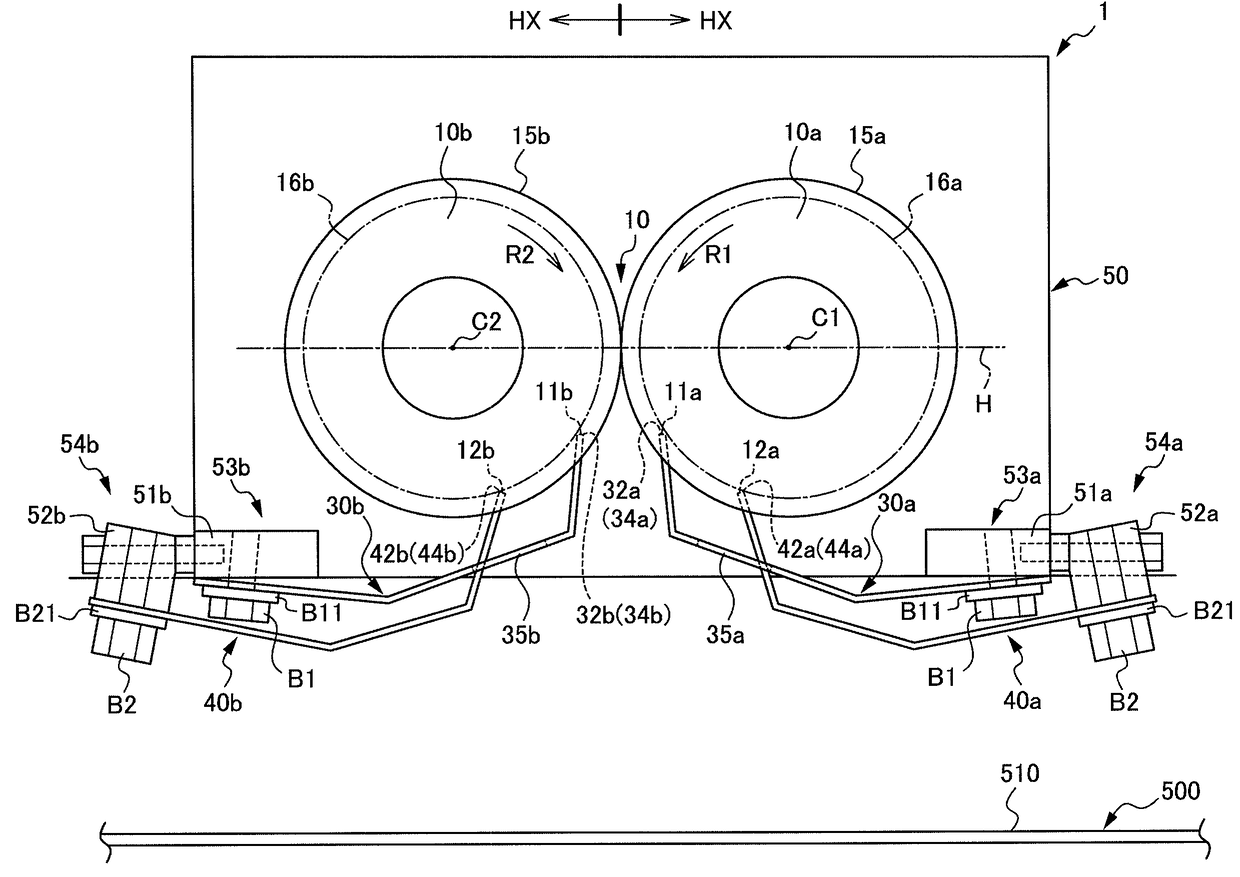
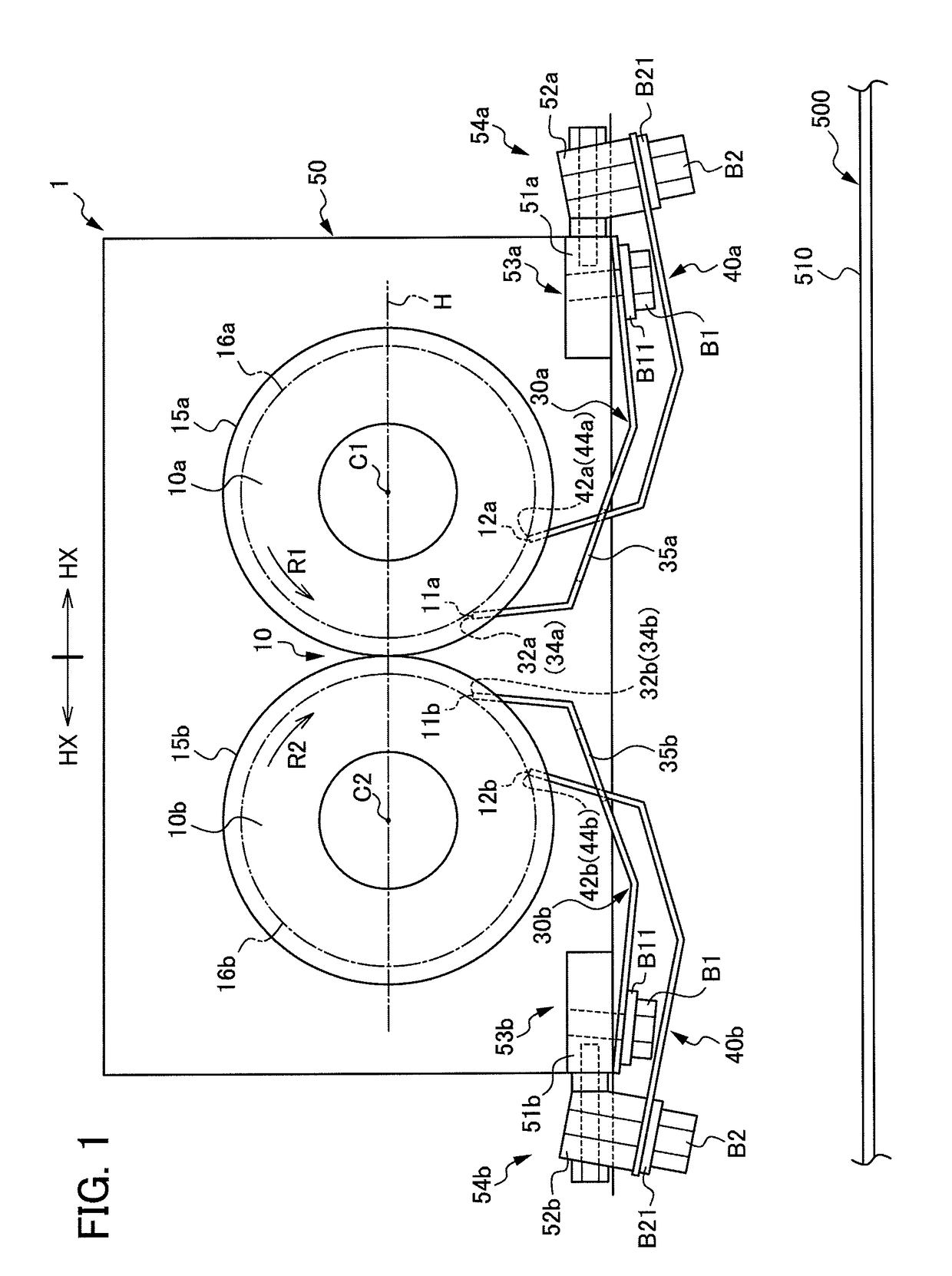
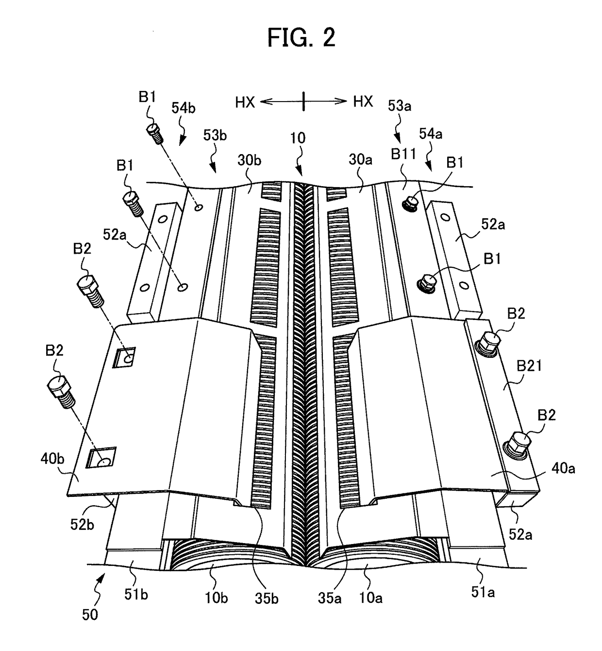
[0042]In the following, a description is given of an apparatus for cutting out noodle according to a first embodiment of the present invention. FIG. 1 is a cross-sectional view illustrating a structure of an apparatus 1 for cutting out noodle according to a first embodiment. FIG. 2 is a perspective view of the apparatus 1 for cutting out noodle shown in FIG. 1, as seen from below. FIG. 3 is a plan view illustrating a first roller 10a having cutting blades 70a and a second roller 10b having cutting blades 70b. FIG. 4 is a partially enlarged view of the first roller 10a and the second roller 10b. FIG. 5 is a view illustrating a meshing state between the first roller 10a and the second roller 10b. FIG. 6 is a perspective view illustrating an arrangement of a first scraper 30a and a second scraper 40a. FIG. 7 is a perspective view showing a state in which the first scraper 30a is separated from the second scraper 40a.

[0043]FIG. 8A is a view illustrating an arrangement of teeth at the f...

second embodiment

[0118]Next, a second embodiment is described. FIG. 13A is a base view showing a first scraper 230a and a second scraper 240 according to a second embodiment. FIG. 13B is a partially enlarged view of FIG. 13A.

[0119]As shown in FIGS. 13A and 13B, compared to the apparatus 1 for cutting out noodle according to the first embodiment, an apparatus according to the second embodiment is mainly different in the number of second scrapers 240a that are disposed in a single first transfer hole 235a.

[0120]More specifically, in the second embodiment, the single first scraper 230a is provided with the single first transfer hole 235a. Accordingly, the first scraper 230a is not provided with a beam-like strip 38a in the first embodiment. Furthermore, the first scraper 230a is not provided with a group of second teeth 37a corresponding to the beam-like strip 38a.

[0121]A length of the first transfer hole 235a in the second embodiment is approximately triple the length of the first transfer hole 35a ...

third embodiment

[0124]Next, a third embodiment is described. FIG. 14A is a base view showing a first scraper 330a and a second scraper 340a according to the third embodiment. FIG. 14B is a partially enlarged view of FIG. 14A.

[0125]As shown in FIGS. 14A and 14B, compared to the apparatus for cutting out noodle according to the second embodiment, an apparatus for cutting out noodle according to the third embodiment is mainly different in that a single first scraper 330a is provided with a single first transfer hole 335a and the single first transfer hole 335a is provided with a single second scraper 340a.

[0126]More specifically, in the third embodiment, the single first scraper 330a is provided with the single first transfer hole 335a similarly to the second embodiment. In addition, a length of the first transfer hole 335a of the third embodiment is approximately triple the length of the first transfer hole 35a of the first embodiment.

[0127]On the other hand, in the third embodiment, a single second...


PUM

PropertyMeasurementUnit
contact angleaaaaaaaaaa
angleaaaaaaaaaa
shapesaaaaaaaaaa

Abstract

An apparatus for cutting out noodle can prevent damage to scraping teeth of a scraper and prevent noodle threads from being caught at a fixing position of the scraper. The apparatus includes a housing, a first roller having a first receiving portion, a second roller having a second receiving portion, a first scraper secured at a first fixing position and having first scraping teeth inserted in the first receiving portion, a second scraper having second scraping teeth, a third scraper secured at a second secured position and having third scraping teeth, and a fourth scraper having fourth scraping teeth. The first and third scrapers include first and second transfer holes, respectively. The first fixing position is located more outwardly in a horizontally outward direction than a second tooth tip, and the third fixing position is located more outwardly in the horizontally outward direction than a fourth tooth tip.

Description

TECHNICAL FIELD[0001]The present invention relates to an apparatus for cutting out a noodle strip into noodle threads by a roller having cutting blades in manufacturing noodles.BACKGROUND ART[0002]Conventionally, as a method for cutting out noodle threads by a machine, a method has been prevailing, in which a thin noodle strip of a belt-like shape rolled from noodle dough travels between a pair of rollers having cutting blades that rotate oppositely to each other such that the thin noodle strip is cut out into a thread shape. Each of the pair of rollers having cutting blades includes a plurality of blades formed in a circumferential direction and a plurality of grooves formed between the blades. A roller having cutting blades includes a plurality of types of blades such as a square blade type, a round blade type, a kitchen knife type, and the like, depending on shapes of noodle threads to be cut out, shapes of teeth tips, and the like.[0003]For example, the square blade type cuts ou...

Claims


Application Information

Patent Timeline
Patent Type & Authority Patents(United States)
IPC IPC(8): A21C11/24B26D1/24B26D7/18
CPCB26D1/245B26D7/1818A21C11/24Y10T83/783Y10T83/21Y10T83/212Y10S83/932A21C11/22
Inventor YOSHIDA, KUNIHIKOMIYAZAKI, YOSHIFUMIYAMAYA, TATSUOTANAKA, MITSURU
Owner NISSIN YORK
Why Eureka
Try Eureka