
Nesting fenders

a fenders and a gencarelli technology, applied in the field of nested fenders, can solve the problems of not teaching individual tubular members and not disclosing arrangement arrangements of gencarelli, and achieve the effects of optimizing storage, maximizing storability, and ensuring tension

Inactive Publication Date: 2018-01-23
CONTACT LEFT LLC
View PDF4 Cites 3 Cited by
  • Summary
  • Abstract
  • Description
  • Claims
  • Application Information

AI Technical Summary

Benefits of technology

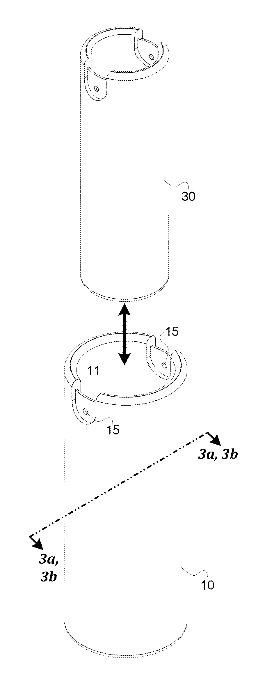
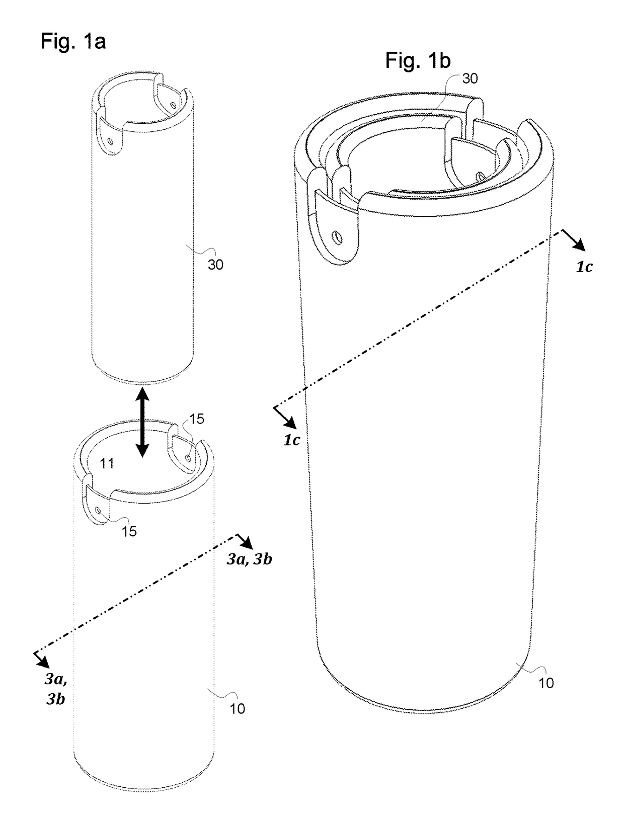
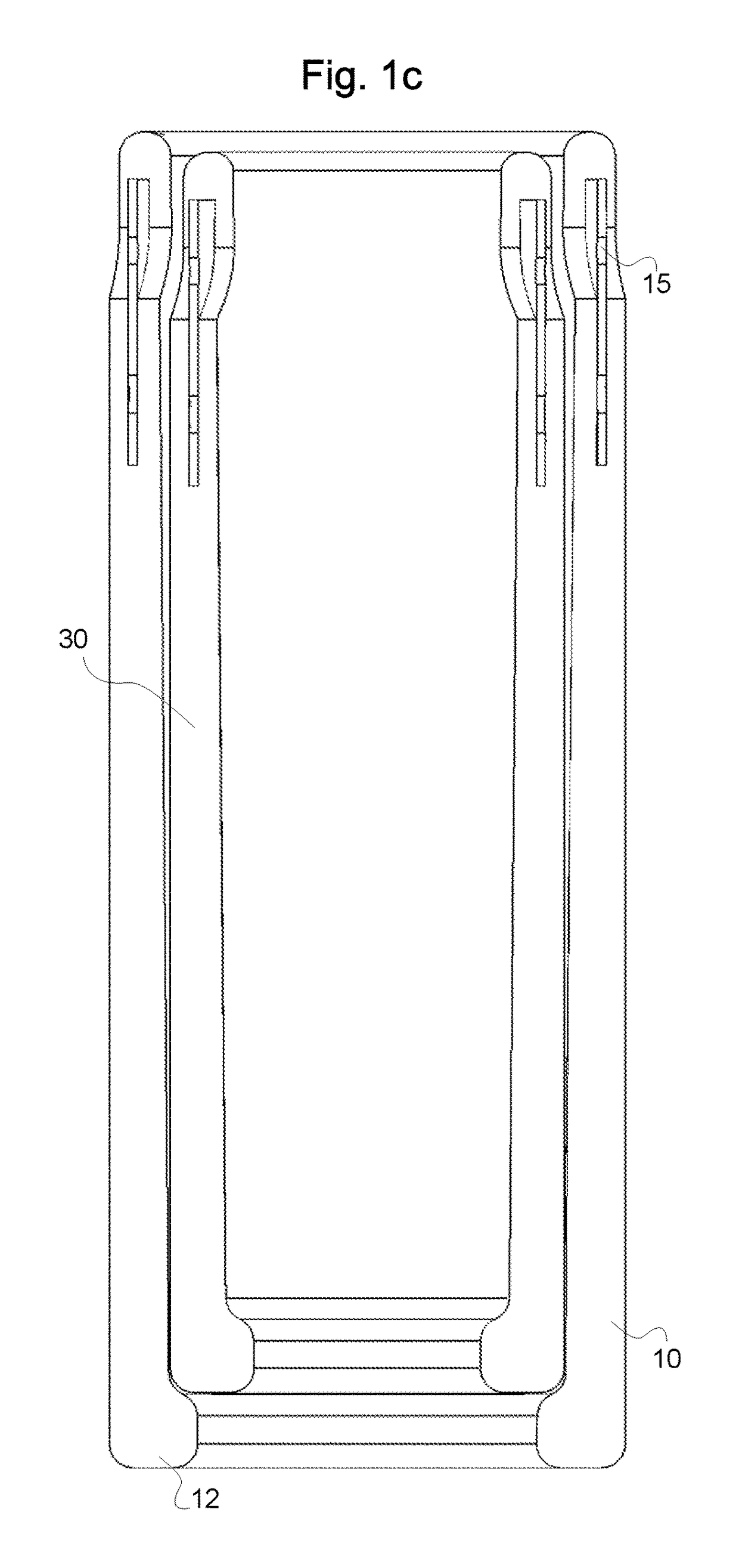
[0012]The relative diameters of the graduated-sized fenders are such that the inner diameter of the cylindrical cavity of a larger fender is substantially the same as the outer diameter of the next sized down fender. The diameters are sized to provide tension between the outer surface of the cylindrical body of the smaller fender and the inner surface of the cylindrical cavity of the larger fender for retention of the smaller fender within the larger fender. The tension provided is such that the fenders will remain nested when at rest or even when displaced by the boat in motion (e.g. if the nested fenders are upside-down) but without so much tension that the fenders are unable to be nested or separated by hand. In addition to providing the tension for keeping the fenders nested, the relative diameters ensure that the entire cavity of the larger fender is utilized by the smaller fender with no wasted interior space, maximizing the storability of the nested fenders. The smallest nesting fender of the set may be sized to receive a commercially-available off-the-shelf fender of the type that does not have an interior cavity, such as an F Series fender manufactured by Polyform US (an example of which is viewable on the World Wide Web at www.polyformus.com / boat-fenders / f-series), ensuring that every volumetric portion of the cavity of the largest fender is used for other fenders and optimizing storability.
[0013]The resulting differently-sized fenders are deployable about the boat for different purposes. For example, the largest fenders may be deployed along a side of the boat adjacent to an immovable jetty, and smaller fenders may be deployed along an opposing side of the boat adjacent to another boat floating in the water. In this way, the fenders may be deployed to optimally absorb the relative impact of the adjacent bodies. The largest fenders, which are capable of absorbing the most impact force, can be placed nearest the immovable object (e.g. a jetty) where impact forces are likely to be largest. Smaller fenders, which can absorb relatively less impact force, are placed nearest to floating objects like other boats where impact forces are likely to be lessened because some energy from impact is consumed by the rebound of the other boat subsequent to impact. In a different usage, the fenders may be deployed in a nested configuration (i.e. a smaller fender within a larger fender) to provide an even stronger unit which is capable of absorbing a relatively larger impact than a single nesting fender acting alone.

Problems solved by technology

Santelli does not disclose an arrangement where an entire fender may fit within another fender for optimally-reduced storage requirements.
Gencarelli does not teach the individual tubular members being deployable as an individual boat fender.

Method used


Image

  • Nesting fenders
  • Nesting fenders
  • Nesting fenders

Examples


Embodiment Construction

[0025]Specific details of certain embodiments of the invention are set forth in the following description and in the figures to provide a thorough understanding of such embodiments. The present invention may have additional embodiments, may be practiced without one or more of the details described for any particular described embodiment, or may have any detail described for one particular embodiment practiced with any other detail described for another embodiment.

[0026]Importantly, a grouping of inventive aspects in any particular “embodiment” within this detailed description, and / or a grouping of limitations in the claims presented herein, is not intended to be a limiting disclosure of those particular aspects and / or limitations to that particular embodiment and / or claim. The inventive entity presenting this disclosure fully intends that any disclosed aspect of any embodiment in the detailed description and / or any claim limitation ever presented relative to the instant disclosure a...


PUM


Abstract

An arrangement of fenders nested together for compact storage, the fenders including two or more cylindrical bodies having a cavity accessed through the fender top, the fenders being similar shape but graduated in size such that the cavity of a larger fender tensionally receives the next smaller sized fender, the outer diameter of the smaller fender equal to the inner diameter of the larger fender cavity. A fender has a rigid inner core surrounded by a compressible shell made of foam or similar material. The inner core has attachment points for a rope or line. The smallest nesting fender in the set has a cavity diameter sized to fit a commercially-available, off-the-shelf fender. The fenders may be separated and deployed at individual locations on a vessel, or kept together and deployed as a single fender capable of absorbing a greater impact than any of the fenders individually would absorb.

Description

PRIORITY CLAIM[0001]The present application is related to and / or claims the benefits of the earliest effective priority date and / or the earliest effective filing date of the below-referenced applications, each of which is hereby incorporated by reference in its entirety, to the extent such subject matter is not inconsistent herewith, as if fully set forth herein:[0002](1) this application constitutes a non-provisional of U.S. Provisional Patent Application No. 62 / 443,738, entitled NESTING FENDERS, naming John D. Denney as the inventor, filed Jan. 8, 2017, which is an application of which is entitled to the benefit of the filing date; and[0003](2) this application constitutes a non-provisional of U.S. Provisional Patent Application No. 62 / 492,852, entitled NESTING FENDERS, naming John D. Denney, Jr. as the inventor, filed May 1, 2017, which is an application of which is entitled to the benefit of the filing date.FIELD OF THE INVENTION[0004]This invention relates generally to marine v...

Claims


Application Information

Patent Timeline
Patent Type & Authority Patents(United States)
IPC IPC(8): B63B59/02E02B3/26
CPCE02B3/26B63B59/02B63C9/26B63B2059/025
Inventor DENNEY, JR., JOHN D.CARRASCA, ROBERTHAMLIN, CHRISTOPHER
Owner CONTACT LEFT LLC
Learn More