Orthodontic gripping device

a technology of orthodontics and gripping devices, which is applied in the field of orthodontics, can solve the problems of difficult field handling and deployment, food to become trapped, irritate the patient's cheeks or gum tissue,

Active Publication Date: 2018-01-30
STRITE INDS
View PDF54 Cites 11 Cited by
  • Summary
  • Abstract
  • Description
  • Claims
  • Application Information

AI Technical Summary

Problems solved by technology

The relatively small size of these types of stops and the fact that they include movable components have tended to make them difficult to handle and deploy in the field.
Moreover, there have been some complaints that once mounted in the mouth these stops tend to be bulky and may irritate the patient's cheek or gum tissue as a result of their bulkiness.
The design of these stops may also allow food to become trapped within the stop or between the stop and the patient's soft tissue or dentition.
Additionally, these stops tend to loosen from, or slip along, the arch wire over time.
Slippage problems have been encountered with these types of stops, as the arch wire tends to slide within the sleeve when forces are applied to it.
However, handling and slippage problems remain.
Threading of the arch wire through the sleeve can be challenging as the arch wire itself has a relatively small cross-sectional area and the passageway formed in the sleeve is also quite small.
Once threaded on the arch wire (and prior to crimping) the sleeve can inadvertently move during crimping thus making precise positioning difficult.

Method used


Image

  • Orthodontic gripping device
  • Orthodontic gripping device
  • Orthodontic gripping device

Examples


first embodiment

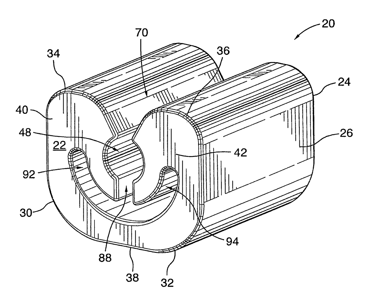
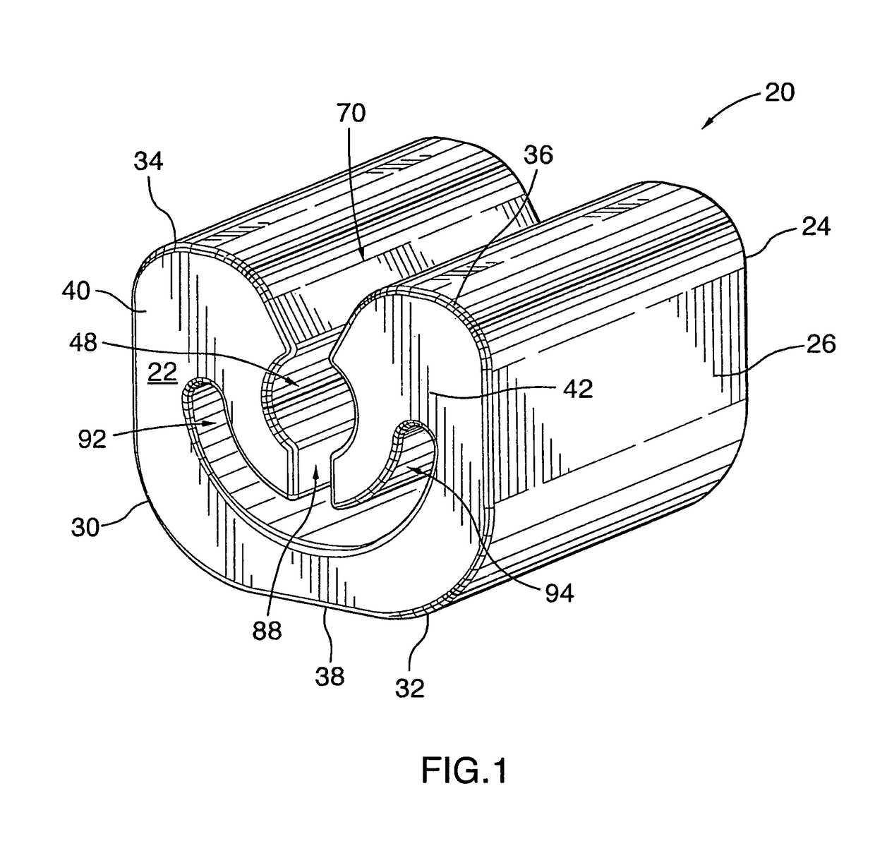
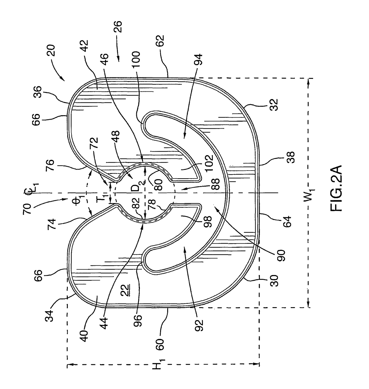
[0070]Referring to FIGS. 1, 2A and 2B, there is shown an orthodontic gripping device in accordance with the present invention designated generally with reference numeral 20. The gripping device 20 is configured for use with an orthodontic arch wire. The orthodontic gripping device 20 includes a mesial face 22, a distal face 24 and an elongate body 26 extending between the mesial and distal faces 22 and 24. In this embodiment, the body 26 is of unitary (one-piece or monolithic) construction fabricated from a superelastic material. Preferably, such material is a superelastic metal alloy. Most preferably, the superelastic metal alloy is nickel titanium, or nickel titanium and other alloying elements (e.g. chromium (Cr), iron (Fe), vanadium (V), aluminium (Al), copper (Cu), cobalt (Co)), such as nickel / titanium / copper or nickel / titanium / copper / chromium. Preferably, the nickel titanium, or nickel titanium and other alloying elements, is cold worked. Although, cold worked and aged nickel ...

second embodiment

[0116]Referring to FIGS. 5A, 5B and 5C, there is shown an orthodontic gripping device constructed in accordance with the principles of the present invention. The gripping device in this embodiment is designated generally with reference numeral 170 and is similar in all material respects (i.e. functionality, configuration and construction) to the gripping device 20 shown in FIGS. 1 to 3, except that gripping device 170 is provided with a hook 172 which depends from the gripping device body 174.

[0117]The body 174 is similar to the body 26 in that it too includes a longitudinal centerline CL1 (shown in FIG. 5B), a transverse centerline CL2 (shown in FIG. 5C), a base portion 176 and a pair of opposed, spaced apart, first and second arm portions 178 and 180 connected to the base portion 176 and disposed on opposite sides of the centerline CL1. The body 174 is symmetrical about the longitudinal centerline CL1 such that the arm portions 178 and 180 are mirror images of each other. The body...

third embodiment

[0124]In the embodiments shown in FIGS. 1 through 5C, the gripping devices 20 and 170 are configured to receive and clamp tightly onto an arch wire of circular cross-section. However, this need not be the case in every application. In a third embodiment illustrated in FIGS. 12 to 17, there is shown an orthodontic gripping device 200 which is configured for use with an arch wire 202 of substantially rectangular cross-section.

[0125]Referring to FIGS. 12, 13A and 13B, the gripping device 200 is generally similar to gripping device 20 described above in that it too has a mesial face 204 and a distal face 206 and an elongate body 208 extending between the mesial and distal faces 204 and 206. In this embodiment, the body 208 is of unitary (one-piece or monolithic) construction fabricated from a superelastic material. Preferably, such material is a superelastic metal alloy. Most preferably, the superelastic metal alloy is nickel titanium, or nickel titanium and other alloying elements (e.g...


PUM


Abstract

The present invention relates to an orthodontic gripping device having a body made of a superelastic metal alloy, cold worked titanium beta III, or solution heat treated and aged titanium beta III. The body has first and second, spaced apart arm portions connected to each other. Each arm portion includes a jaw portion having an inner, arch wire-gripping, surface. The inner gripping surfaces are disposed opposite one another in spaced relation with a station defined therebetween for receiving the arch wire. At least a portion of the station is sized smaller than the arch wire. The arm portions are resiliently deflectable outwardly away from each other to admit the arch wire into the station. Once seated in the station, the arch wire is tightly held by inner gripping surfaces so as to resist displacement of the gripping device relative to the arch wire.

Description

CROSS-REFERENCE APPLICATIONS[0001]The present invention claims priority under 35 U.S.C. §120 to U.S. Provisional Patent Application No. 61 / 457,013, filed on Dec. 8, 2010, the disclosure of which is incorporated by reference herein in its entirety.FIELD OF THE INVENTION[0002]The present invention relates to the field of orthodontics, in particular, to an orthodontic gripping device suitable for tightly clamping onto an arch wire or other orthodontic component.BACKGROUND OF THE INVENTION[0003]In orthodontics, an arch wire is used in conjunction with orthodontic brackets mounted to the patient's teeth to move the teeth to desired positions. The arch wire is configured to conform generally to the dental arch of the patient and is accommodated or seated within arch wire slots defined in the orthodontic brackets. The arch wire exerts forces on the orthodontic brackets which over time cause the teeth to move to their correct positions.[0004]In orthodontic treatment, it is customary to plac...

Claims


Application Information

Patent Timeline
Patent Type & Authority Patents(United States)
IPC IPC(8): A61C3/00A61C7/20A61C7/04A61C7/02A61C7/22
CPCA61C7/02A61C7/22A61C7/20A61C7/04A61C2201/007A61C7/28A61L31/022
Inventor CHESTER, NEIL
Owner STRITE INDS
Why Eureka
Try Eureka