Methods for forming fiber reinforced composite parts having one or more selectively positioned core, structural insert, or veneer pieces integrally associated therewith

a fiber reinforced composite material and selective positioning technology, applied in the field of hollow fiber reinforced composite material components and parts, can solve the problems of little advancement in the field of methods for forming hollow composite material components or parts, little development in the field of methods for forming hollow composite material parts, and the method is not entirely satisfactory for forming high-precision parts with exact specifications and tolerances

Active Publication Date: 2009-12-29
FREL KENNETH A
View PDF20 Cites 9 Cited by
  • Summary
  • Abstract
  • Description
  • Claims
  • Application Information

AI Technical Summary

Problems solved by technology

Although composite material molding is, in some respects, well known in the art, there has been little advancement with respect to methods for forming hollow composite material components or parts, especially hollow composite material components or parts having complex surface geometries or shapes.
Additionally, there has likewise been little development with respect to methods for forming hollow composite material parts that have been structurally or cosmetically enhanced by the addition of selectively positioned core, structural insert, or veneer pieces.
For example, U.S. Pat. No. 4,202,856 to Frikken et al. teaches one method for forming a hollow composite material part, but this method is not entirely satisfactory for forming high-precision parts with exacting specifications and tolerances.
More specifically, the method taught by U.S. Pat. No. 4,202,856 to Frikken et al. is not entirely satisfactory for forming hollow parts having complex surface geometries because, among other reasons, the disclosed pressure bag (i.e., bladder) does not generally fit snuggly about the underlying mandrel (thereby making it more difficult and less exacting to uniformly apply resin, fibers, and / or core pieces about the mandrel).
Moreover, and upon pressurization, the loosely fitting pressure bag poorly and nonconformally forces the uncured composite material into angular recesses of the mold thereby resulting in non-uniformity of material at those sites.
The methods disclosed in these patents, however, are also not entirely satisfactory for forming hollow parts having complex surface geometries because, among other reasons, the disclosed flexible (but inherently “non-elastic”) thin-film bladders used in these methods also do not fit snuggly about the mandrel (meaning that the disclosed bladders in these methods, without application of vacuum, are similarly nonconformal to the shape of the mandrel).
As such, these methods are also not generally amenable for forming hollow composite material parts having one or more selectively positioned core, structural insert, or veneer pieces integrally associated therewith because placement of such pieces about the bladdered mandrel is very inexact.
In addition, the flexible but non-elastic thin-film bladders disclosed in these methods also, upon pressurization, poorly and non-uniformly forces the uncured composite material into angular recesses of the mold.
Thus, existing state-of-the-art molding systems and related methodologies are not entirely satisfactory for the fabrication of high-precision hollow composite material components or parts, especially those components or parts having complex surface geometries and having one or more core, structural insert, or veneer pieces integrally associated therewith.
Moreover, existing molding methodologies have not addressed many of the concomitant problems associated with selectively positioning one or more core pieces on or within the formed hollow composite material components or parts.

Method used


Image

  • Methods for forming fiber reinforced composite parts having one or more selectively positioned core, structural insert, or veneer pieces integrally associated therewith
  • Methods for forming fiber reinforced composite parts having one or more selectively positioned core, structural insert, or veneer pieces integrally associated therewith
  • Methods for forming fiber reinforced composite parts having one or more selectively positioned core, structural insert, or veneer pieces integrally associated therewith

Examples


Embodiment Construction

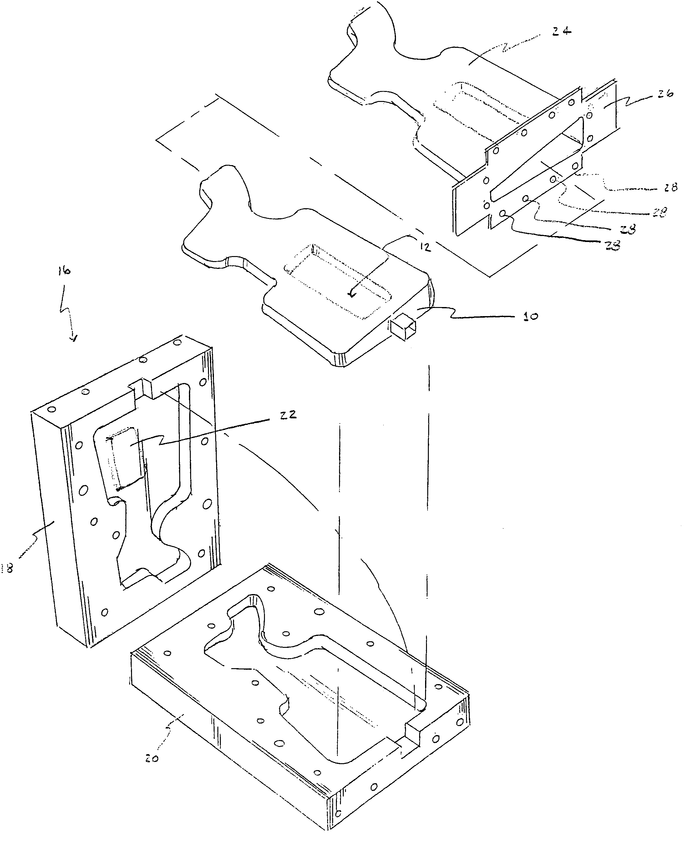
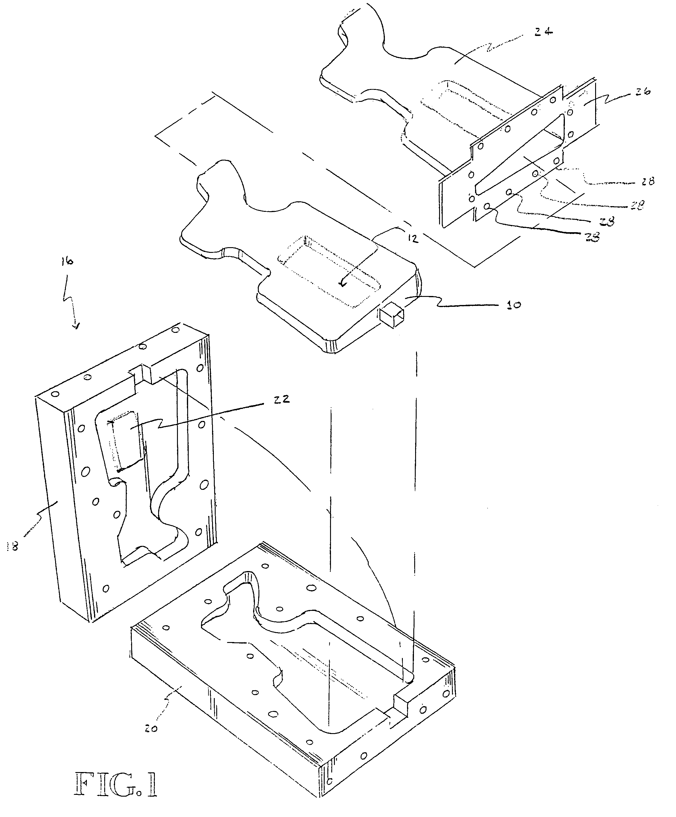
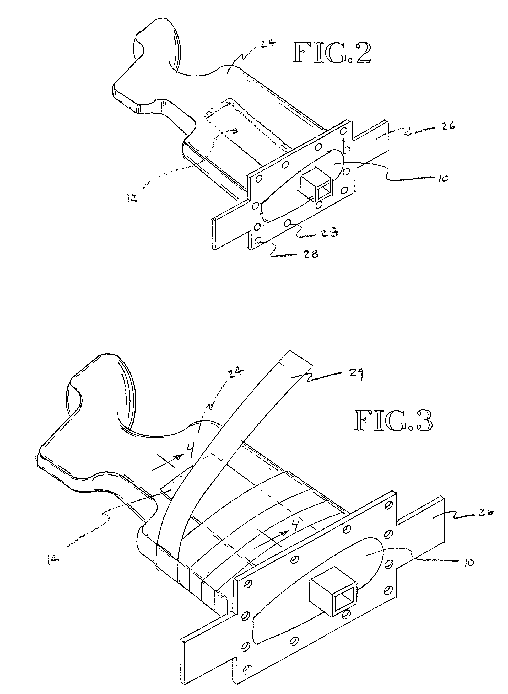
[0019]As noted above, the present invention relates generally to methods for forming hollow components and parts made of fiber reinforced composite materials and, more specifically, to hollow fiber reinforced composite material parts having one or more selectively positioned core, structural insert, or veneer pieces integrally associated therewith. As is appreciated by those skilled in the art, a composite material part is generally made by molding a plurality of fibers together with an appropriately selected resin. Within the context of the present invention, the plurality of fibers may be woven together so as to form a yam, a fabric or a cloth such as a braid (all of which are encompassed by the term “fiber material”). The principal fibers and fiber materials useful in the context of the present invention include those made of glass (preferably S-glass or E-glass), KEVLAR, carbon, boron, or silicon carbide. In addition, the principal resins include thermoplastic resins such as, fo...


PUM

PropertyMeasurementUnit
pressureaaaaaaaaaa
temperatureaaaaaaaaaa
timeaaaaaaaaaa

Abstract

The invention disclosed herein relates to hollow fiber reinforced composite material parts having one or more selectively positioned core, structural insert, or veneer pieces integrally associated therewith. In one embodiment, the composite part defines a first shape and the method comprises at least the following steps: providing a mandrel that is substantially the same as but sized smaller than the first shape of the composite material part, wherein the mandrel has one or more selectively positioned complementary recesses; forming an elastic layer about the mandrel to define an elastic bladder; applying a vacuum in between the bladder and the mandrel to thereby force and conform the bladder against the exterior surface of the mandrel; applying a resin and a fiber material about the bladder, and positioning at least one of the one or more core, structural insert, or veneer pieces adjacent and proximate to one of the one or more selectively positioned recesses to define an uncured part; placing the uncured part into a mold; applying a fluid or gas pressure in between the mandrel and the uncured part to thereby force and conform the uncured part against the interior surface of the mold; and heating the mold to a temperature and for a period of time sufficient to cure the resin to thereby define the hollow composite material part.

Description

TECHNICAL FIELD[0001]The present invention relates generally to methods for forming hollow components and parts made of fiber reinforced composite materials and, more specifically, to hollow fiber reinforced composite material components and parts including those having one or more selectively positioned core, structural insert, or veneer pieces integrally associated therewith.BACKGROUND OF THE INVENTION[0002]The economic importance of composite materials is well known, and there are strong indications that this importance will be increasing into the future. In this regard, and for example, composite materials are being used with increasing frequency in the automotive, naval construction, and aerospace industries. As used herein, the term composite material simply refers to materials made of strong fibers (continuous or noncontinuous) surrounded by a matrix material, wherein the matrix material serves to distribute and secure the fibers and to facilitate transmission of an applied l...

Claims


Application Information

Patent Timeline
Patent Type & Authority Patents(United States)
IPC IPC(8): B32B37/00B28B7/30B29C70/00B29C70/32B29C70/34B29C70/44B29C70/86
CPCB29C70/32B29C70/86B29C70/446B29C70/342
Inventor FRANKEL, KENNETH A.
Owner FREL KENNETH A
Why Eureka
Try Eureka